Fuel Pump Solution - All Failure Modes
#1
Fuel Pump Solution - All Failure Modes
UPDATE for by ''Scottish''...Quotes..
I've gone through a Walbro and now a DW200 and still the same problems.
THE DIFINITIVE FIX FOR FUEL CUT ON HIGH G LEFTS AND ANY RANDOM LOSS OF FUEL PRESSURE IN A LOWER END HP BOOSTED, STREET, LIGHT TRACK DUTY CAR IS TO ONLY USE A BRAND NEW SLIGHTLY MODDED TO FIT SERIES 2 FUEL PUMP ASSEMBLY.
DO NOT PUT HIGH FLOW PUMPS IN A SERIES 1 ASSEMBLY IT DOES NOT WORK. I HAVE DONE IT TWICE NOW AND IT STILL DOESN'T WORK!
SERIES 2 OEM Fuel Pump Assembly part no. N3R1-13-35Z Some Modifications to fit in a Series 1 fuel tank is required.
End of Scottish quotes in 2014.
.................................................. .................................................. .................................................. .................................................. .................................................. .
This thread is intended to answer some questions about the function (or lack thereof) of the OE RX-8 fuel pump assembly as it is employed on the 2008 and earlier models.
There is a lot of speculation out there about pump efficacy, volume and the function of the siphon system for the saddle-style fuel tank as well as some pretty wild conjecture about the filtration parts, pressure regulation and the control electronics.
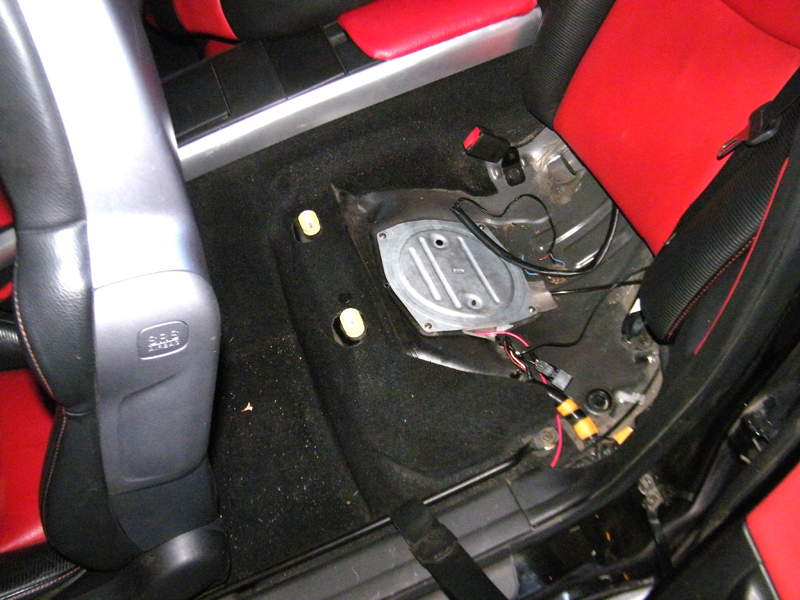
The fuel pump assembly is located under an access panel beneath the left-side rear passenger seat. The lower seat cushion simply pulls up and the panel beneath is held in place by 4 sheet metal screws. Since the pump is a "dead-end" style, self-regulating assembly, there is only a single discharge outlet and no return inlet. There is a single electrical connector on the pump assembly that provides power to the pump and readings from the left-side tank level sensor.
The pump assembly is mounted to the tank and held in place via a clamp ring that is removed with a "special service tool". This ring clamps the pump's upper section to the opening on the tank and against a stacked set of "O" rings.

The pump is controlled by a "two-step" electrical regulation scheme under PCM control. Two relays in the main fuse box under the hood provide current to the pump in two stages - the initial low-load/start-up/idle output is on the "CIRCUIT" relay and the high-load output is on the "FUEL" relay.
Current from the "CIRCUIT" relay passes through a .34 OHM power resistor located on the air pump assembly bracket prior to powering the pump. This resistor lowers the pump voltage by about 2 volts from the alternator's ~14v output. Current from the "FUEL" relay goes directly to the pump, bypassing the resistor.
Under command from the PCM, these relays close based on current vehicle operating conditions.
The "CIRCUIT" relay is closed at all times that the engine is running or being cranked. It is open (off) when the key is in the "RUN" position and the motor is not running. It also switches off should the engine stop running for any reason or the roll-over sensor in the fuel tank is tripped.
The "FUEL" relay closes around the same time and conditions under which the secondary fuel injectors are enabled, upping the pump pressure output by about 15%.
This scheme is employed purely to reduce noise from the pump and fuel vapor emissions and is NOT a wear-reducing countermeasure. Most modern performance vehicles with an electric fuel pump employ this scheme.

The pump assembly itself is comprised of 5 main components:
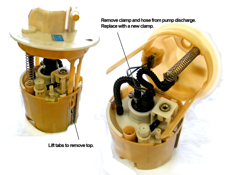
The spring-loaded upper section which has the discharge fitting and external connector, the lower fuel "bowl", which accumulates and retains fuel prior to being picked up by the pump, the pressurized main filter and integral fuel pressure regulator, the regulator discharge and siphon assembly and the pump motor itself.
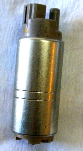
The pump motor is a ~115 lph (nominal) unit made by Arram. When current is applied, it draws fuel in from its pick-up port on the bottom through a plastic filter "sock" that blocks larger particles of crud from entering the fuel system. The fuel is discharged from the upper port under pressure.
Pressure and flow are, of course, inversely proportional, so the volume of fuel that is moved by the pump is a function of the pressure developed after the pump. This pressure is regulated by the main filter and integral fuel pressure regulator, into which the pumps output is sent.
The main filter and integral fuel pressure regulator has three ports: the inlet, the outlet and the pressure regulator discharge.
Fuel is pumped into the main filter assembly and exits the discharge at a rate determined by the integral pressure regulator (about 60 PSI).
When the pressure inside the filter exceeds the regulator setting, fuel is sent back to the fuel bowl via the regulator discharge and siphon assembly.
Fuel passes through a venturi on its way back to the bowl, generating suction on the siphon tube fitting. If excess pressure is generated by the small venturi orifice, it is bled off through a spring-loaded pop-off valve on the top of the assembly.
This is, in a properly operating pump assembly, a continuous operation - fuel is always flowing out of the main filter and through the siphon assembly as the pump should be producing more than 60 PSI at the required flow at all times.
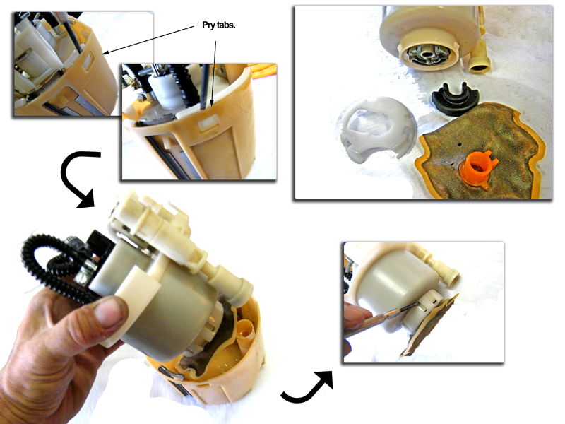
There are essentially 3 failure modes observed with this pump assembly:
Though much has been discussed on this forum with regards to the causes of these failures - filter clogging, misalignment of the assembly in the tank, crimped or disconnected siphon hoses, clogging from the use of pre-mix, etc. - all can actually be attributed to partial failure of the pump motor itself.
In every pump I have tested - some that were removed because of these failures, some as regular maintenance and some that were still in service - the pump motor could not keep up with demand under all circumstances.
In many, the pump never produced enough pressure to open the regulator at all. This means that no fuel was servicing the siphon, so no fuel was being moved from the right-side tank to the left-side.
Not a single pump had enough "blockage" of either filter element to restrict flow were the pump up to task. In fact, the sealed main filter cannot restrict flow significantly even if it were somehow completely clogged! The assembly is constructed in such a manner that fuel will flow around the element as it becomes a restriction (something that NONE of the pumps tested had done - even units that were replaced for that very reason by the owner of the vehicle).
Solutions suggested to date:
1) Dismantle and clean the filter elements
The 09+ assembly addresses some of the siphon issues, but is still designed to provide about 115 lph. A 350 HP+ Renesis will need closer to 200 lph.
Fortunately, the solution for ALL fuel pump issues is relatively easy and inexpensive: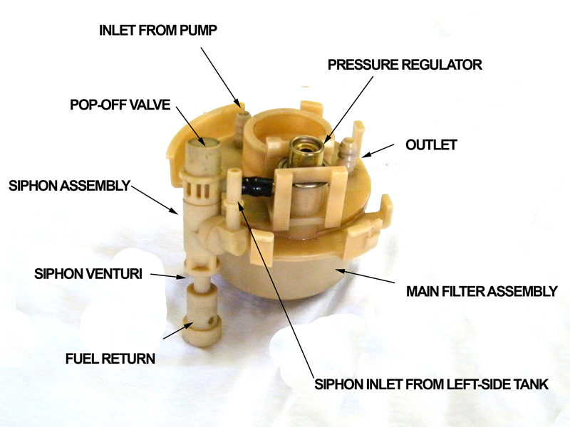
The OE siphon assembly cannot take the elevated relief pressures as it stands, so the pop-off valve cap on top of the siphon must be melted on with a hot piece of metal or something similar to keep it in place. Reassemble and reinstall.
Removal and installation of the pump unit is well covered elsewhere on this forum.
I've gone through a Walbro and now a DW200 and still the same problems.
THE DIFINITIVE FIX FOR FUEL CUT ON HIGH G LEFTS AND ANY RANDOM LOSS OF FUEL PRESSURE IN A LOWER END HP BOOSTED, STREET, LIGHT TRACK DUTY CAR IS TO ONLY USE A BRAND NEW SLIGHTLY MODDED TO FIT SERIES 2 FUEL PUMP ASSEMBLY.
DO NOT PUT HIGH FLOW PUMPS IN A SERIES 1 ASSEMBLY IT DOES NOT WORK. I HAVE DONE IT TWICE NOW AND IT STILL DOESN'T WORK!
SERIES 2 OEM Fuel Pump Assembly part no. N3R1-13-35Z Some Modifications to fit in a Series 1 fuel tank is required.
End of Scottish quotes in 2014.
.................................................. .................................................. .................................................. .................................................. .................................................. .
This thread is intended to answer some questions about the function (or lack thereof) of the OE RX-8 fuel pump assembly as it is employed on the 2008 and earlier models.
There is a lot of speculation out there about pump efficacy, volume and the function of the siphon system for the saddle-style fuel tank as well as some pretty wild conjecture about the filtration parts, pressure regulation and the control electronics.

The fuel pump assembly is located under an access panel beneath the left-side rear passenger seat. The lower seat cushion simply pulls up and the panel beneath is held in place by 4 sheet metal screws. Since the pump is a "dead-end" style, self-regulating assembly, there is only a single discharge outlet and no return inlet. There is a single electrical connector on the pump assembly that provides power to the pump and readings from the left-side tank level sensor.
The pump assembly is mounted to the tank and held in place via a clamp ring that is removed with a "special service tool". This ring clamps the pump's upper section to the opening on the tank and against a stacked set of "O" rings.

The pump is controlled by a "two-step" electrical regulation scheme under PCM control. Two relays in the main fuse box under the hood provide current to the pump in two stages - the initial low-load/start-up/idle output is on the "CIRCUIT" relay and the high-load output is on the "FUEL" relay.
Current from the "CIRCUIT" relay passes through a .34 OHM power resistor located on the air pump assembly bracket prior to powering the pump. This resistor lowers the pump voltage by about 2 volts from the alternator's ~14v output. Current from the "FUEL" relay goes directly to the pump, bypassing the resistor.
Under command from the PCM, these relays close based on current vehicle operating conditions.
The "CIRCUIT" relay is closed at all times that the engine is running or being cranked. It is open (off) when the key is in the "RUN" position and the motor is not running. It also switches off should the engine stop running for any reason or the roll-over sensor in the fuel tank is tripped.
The "FUEL" relay closes around the same time and conditions under which the secondary fuel injectors are enabled, upping the pump pressure output by about 15%.
This scheme is employed purely to reduce noise from the pump and fuel vapor emissions and is NOT a wear-reducing countermeasure. Most modern performance vehicles with an electric fuel pump employ this scheme.

The pump assembly itself is comprised of 5 main components:
The spring-loaded upper section which has the discharge fitting and external connector, the lower fuel "bowl", which accumulates and retains fuel prior to being picked up by the pump, the pressurized main filter and integral fuel pressure regulator, the regulator discharge and siphon assembly and the pump motor itself.

The pump motor is a ~115 lph (nominal) unit made by Arram. When current is applied, it draws fuel in from its pick-up port on the bottom through a plastic filter "sock" that blocks larger particles of crud from entering the fuel system. The fuel is discharged from the upper port under pressure.
Pressure and flow are, of course, inversely proportional, so the volume of fuel that is moved by the pump is a function of the pressure developed after the pump. This pressure is regulated by the main filter and integral fuel pressure regulator, into which the pumps output is sent.
The main filter and integral fuel pressure regulator has three ports: the inlet, the outlet and the pressure regulator discharge.
Fuel is pumped into the main filter assembly and exits the discharge at a rate determined by the integral pressure regulator (about 60 PSI).
When the pressure inside the filter exceeds the regulator setting, fuel is sent back to the fuel bowl via the regulator discharge and siphon assembly.
Fuel passes through a venturi on its way back to the bowl, generating suction on the siphon tube fitting. If excess pressure is generated by the small venturi orifice, it is bled off through a spring-loaded pop-off valve on the top of the assembly.
This is, in a properly operating pump assembly, a continuous operation - fuel is always flowing out of the main filter and through the siphon assembly as the pump should be producing more than 60 PSI at the required flow at all times.


There are essentially 3 failure modes observed with this pump assembly:
1)Loss of flow during normal operation after extended highway cruising
2)Loss of flow during relatively high-G left-hand turns
3)Loss of flow during normal operation after 60k miles or more
Additionally, a drop in pressure may be noted during high demand and will adversely affect engine output and AFRs. Those tuning their PCM may note fairly extreme deviations from commanded fuel values at higher loads.2)Loss of flow during relatively high-G left-hand turns
3)Loss of flow during normal operation after 60k miles or more
Though much has been discussed on this forum with regards to the causes of these failures - filter clogging, misalignment of the assembly in the tank, crimped or disconnected siphon hoses, clogging from the use of pre-mix, etc. - all can actually be attributed to partial failure of the pump motor itself.
In every pump I have tested - some that were removed because of these failures, some as regular maintenance and some that were still in service - the pump motor could not keep up with demand under all circumstances.
In many, the pump never produced enough pressure to open the regulator at all. This means that no fuel was servicing the siphon, so no fuel was being moved from the right-side tank to the left-side.
Not a single pump had enough "blockage" of either filter element to restrict flow were the pump up to task. In fact, the sealed main filter cannot restrict flow significantly even if it were somehow completely clogged! The assembly is constructed in such a manner that fuel will flow around the element as it becomes a restriction (something that NONE of the pumps tested had done - even units that were replaced for that very reason by the owner of the vehicle).
Solutions suggested to date:
1) Dismantle and clean the filter elements
As noted, the main filter is not serviceable and wouldn't contribute to reduced pump output even if it became completely blocked. The "sock" on the bottom of the pump motor is serviceable, but none of the pumps I inspected were blocked. Some were dirty or contaminated, but offered no noticeable restriction to pump flow.
2) Replace the entire unit with a new OE unit So far the most practical solution. At ~$135, it is relatively easy and requires very little action on the part of the user. However, it does not address the under-performing pump motor itself and it will eventually fail again.
3) Replace the entire unit with a new 2009+ OE unit Also a good possibility. The newer pump system uses a superior Denso pump instead of the Arram and inverts the venturi/bypass mechanism function. At ~$250 or so, it is a bit more expensive and requires some wiring and placement of the pump in a manner that differs with its intended application and orientation.
None of these solutions address the fundamental issue that the OE pump is designed to just barely fulfill the fueling requirements for 250 - 300 HP and probably only does so for a short period of time. Additionally, the OE siphon system will only continue to work as long as the pump is surpassing the fuel demands of the motor. As soon as its output is below demand, the siphon will stop working again. If you are racing and in a high-G left hand turn while accelerating in a high-output RX-8, you will almost immediately starve the pump.The 09+ assembly addresses some of the siphon issues, but is still designed to provide about 115 lph. A 350 HP+ Renesis will need closer to 200 lph.
Fortunately, the solution for ALL fuel pump issues is relatively easy and inexpensive:
Simply modify the siphon assembly for greater flow and install a high-output pump motor.

The OE siphon assembly cannot take the elevated relief pressures as it stands, so the pop-off valve cap on top of the siphon must be melted on with a hot piece of metal or something similar to keep it in place. Reassemble and reinstall.
Removal and installation of the pump unit is well covered elsewhere on this forum.
Last edited by ASH8; 05-27-2015 at 12:19 AM.
The following users liked this post:
exportsodas (06-10-2023)
#3
Thanks.
Dunno. If there is a demand to have it done, I suppose so. ITs more likely that one of the other vendors will get up and run with it since there is very little profit in it.
Yes. It was the pump. I was losing almost all of my fuel pressure in boost.
Dunno. If there is a demand to have it done, I suppose so. ITs more likely that one of the other vendors will get up and run with it since there is very little profit in it.
Yes. It was the pump. I was losing almost all of my fuel pressure in boost.
#4
If anyone races their 8 and is running a boosted application I strongly suggest the new pump. After seeing Jeff's car starve for fuel on the track and the lean AFRs in low boost he had I am going to look into this pump. If some are not constantly monitoring their AFRs while doing heavy load driving they may not know they are running lean until a datalog is done. It didn't take long for Jeff's car to start running lean. I think many who are running lean sparatically feel it may be a tuning issue when in fact the pump is the problem.
Last edited by Cattywampus; 06-17-2009 at 08:27 PM.
#6
Thanks. I probably forgot something important, though.
Yeah. Don't need it now.
Yes. ESPECIALLY IMPORTANT POINT.
Last edited by MazdaManiac; 06-17-2009 at 08:29 PM.
#7
Registered
iTrader: (4)
Joined: Aug 2004
Posts: 12,255
Likes: 7
From: Buddhist Monastery, High Himalaya Mtns. of Tibet
Good job Jeff,
I wondered what you were up to when you were requesting all those old fuel pumps. I'm one step closer to going to the track again.
Made a Sticky.
I wondered what you were up to when you were requesting all those old fuel pumps. I'm one step closer to going to the track again.
Made a Sticky.
Last edited by alnielsen; 06-17-2009 at 08:39 PM.
#9
I was hoping you were going to take apart a walbro so you could prove your previous assertion that all walbro's were centrifugal pumps. https://www.rx8club.com/showpost.php...&postcount=210
Darn.
Anyway, you were wrong. But you probably already knew that.

More pics and details on the thread I posted yesterday on rotarycarclub.com
http://rotarycarclub.com/rotary_foru...ead.php?t=8329
Darn.
Anyway, you were wrong. But you probably already knew that.

More pics and details on the thread I posted yesterday on rotarycarclub.com
http://rotarycarclub.com/rotary_foru...ead.php?t=8329
#10
I was hoping you were going to take apart a walbro so you could prove your previous assertion that all walbro's were centrifugal pumps. https://www.rx8club.com/showpost.php...&postcount=210
Darn.
Anyway, you were wrong. But you probably already knew that.
Attachment 140690
More pics and details on the thread I posted yesterday on rotarycarclub.com
http://rotarycarclub.com/rotary_foru...ead.php?t=8329
Darn.
Anyway, you were wrong. But you probably already knew that.
Attachment 140690
More pics and details on the thread I posted yesterday on rotarycarclub.com
http://rotarycarclub.com/rotary_foru...ead.php?t=8329
#11
Nope. I was totally wrong.
The Walbros are gerotor pumps.
The Arrams are centrifugal. The Densos are Wesco.
Facts are still the same with regards to flow/pressure, though.
Its interesting that the Walbro you cut up was a 8:9. Their patent calls for a 4:5.
If you have a bunch of time to cut up pumps, I can give you some Densos and Arrams to cut up.
Last edited by MazdaManiac; 06-18-2009 at 01:10 AM.
#12
I figured we might wanna wait. Let the market reveal itself.
Besides, it's not "tested and proven" yet!
#14
lol. U r so l33t!
Seriously though - after I've lived with this a little longer and can see if there are any bugs to worry about, I suppose we should look into whether we can make it more convenient and cost-effective for people that want to make the swap.
So far, there are only upsides (well, now there are, after I figured out the things I did wrong).
#16
lol. U r so l33t!
Seriously though - after I've lived with this a little longer and can see if there are any bugs to worry about, I suppose we should look into whether we can make it more convenient and cost-effective for people that want to make the swap.
So far, there are only upsides (well, now there are, after I figured out the things I did wrong).
Seriously though - after I've lived with this a little longer and can see if there are any bugs to worry about, I suppose we should look into whether we can make it more convenient and cost-effective for people that want to make the swap.
So far, there are only upsides (well, now there are, after I figured out the things I did wrong).
Great write up!
#17
Nice write-up Jeff!
This was a good read and I'll be following this closely because this is something I would like to do eventually before FI (if all goes well with your testing).
This was a good read and I'll be following this closely because this is something I would like to do eventually before FI (if all goes well with your testing).
#20
Really nice write up, the syphon mod is something i never thought of and i will immediately drill it on my car.
Just a heads up for you Jeff with the walbro, we tested some of them and they are not holding their max output well. Anything above the 400hp mark should aim at an even bigger pump in our case imho.
The only problem is that the bigger pumps usually are external units, and that sucks
Also, any advice on which walbro to get for a common user? You know that there are both high and low pressure ones, a bit of help for the average user would avoid bad shopping

#21
There is only one unit that is the proper drop-in replacement.
If it is good enough for a 700 HP Mustang Cobra, its probably good enough for a turbo RX-8!
The only issue I've had so far is that anti-drain-back valve on my pump is intermittent.
I don't know if its defective or if I tweaked it somehow.
If it is good enough for a 700 HP Mustang Cobra, its probably good enough for a turbo RX-8!
The only issue I've had so far is that anti-drain-back valve on my pump is intermittent.
I don't know if its defective or if I tweaked it somehow.
#22
Nice writeup Jeff. Pictures are always good too! This actually stresses something that I think many people have forgotten. In the old carb days when there was a problem, it could really only be a couple of things, ignition or fuel. More people paid attention back then to fuel pressures and timing. Of course that's really all they had to work with too. Today so many people get caught up in all of the ecu functions that they sometimes forget the most basic and important aspects of making power. You've got to have fuel and you've got to be able to ignite it. This mod along with the BHR coils addresses the 2 most important aspects of making power and they shouldn't be overlooked just because an engine is not boosted.
#23
700hp mustang... i wouldn't trust my engine to a walbro in that case either. You know that i've been doing some research as well, ending up with a custom pump made. Well, the reason why i didn't simply buy a walbro is because we encountered some problem on the race cars that used them.
Then we swapped to the bosch 044 and finally to the one i had this guys craft. Our race cars are not even rx8s but after a couple of broken walbros we decided to do some research
Anyway a rotary engine is usually thirstier than its piston counter part as i stated, thus requiring more fuel per HP.
Let me know how you find the walbro to be, maybe we were just unlucky!
@rotarygod: completely true, i have a naturally aspirated rx8 and experienced a lot of problems with the stock fuel pump. It can meet the requirements for a "gran touring" car, which the rx8 is... well, kind of!, but after many sessions at the track it simply stops working the way it should. Overheating is a real pain in that case.
Then we swapped to the bosch 044 and finally to the one i had this guys craft. Our race cars are not even rx8s but after a couple of broken walbros we decided to do some research

Anyway a rotary engine is usually thirstier than its piston counter part as i stated, thus requiring more fuel per HP.
Let me know how you find the walbro to be, maybe we were just unlucky!
@rotarygod: completely true, i have a naturally aspirated rx8 and experienced a lot of problems with the stock fuel pump. It can meet the requirements for a "gran touring" car, which the rx8 is... well, kind of!, but after many sessions at the track it simply stops working the way it should. Overheating is a real pain in that case.
Last edited by bse50; 06-18-2009 at 02:45 PM.
#24
It is VERY likely that, being in Europe, the "Walbro" pumps you are receiving are actually Chinese fakes.
It seems (from somewhat anecdotal evidence) that the fakes are out-numbering the genuine pumps by a factor of two to one.
Its is a dismal situation.
The only insurance you really have is to either purchase directly from Walbro or use a trusted source that purchases directly from Walbro.
As posted elsewhere:
http://www.fuel-pumps.net/walbro-forgeries.html
The following users liked this post:
acbauza (05-13-2019)
#25
Yep, there are many fakes around but we get them through walbro's dealer for "our" team. I said our but i don't work with them.. i just help them with rotaries 
Anyway the prototype is on its way to Charles' so you'll have a chance to see\test it too!

Anyway the prototype is on its way to Charles' so you'll have a chance to see\test it too!


