When you click on links to various merchants on this site and make a purchase, this can result in this site earning a commission. Affiliate programs and affiliations include, but are not limited to, the eBay Partner Network.
Hi. This'll probably take multiple posts to describe everything I want to, but I have successfully downloaded and reflashed the ECU, but I need motivation to clean up publish my code, which right now is basically a bunch of stub code stringed together. I culled a bunch of different sources and have a terribly organized notes.txt with data that originated on various forums - but I want to try and consolidate the data in one thread.
The S1 ECU is a SH7055 originally made by Hitachi, but then spun off / sold to a company called Renesas. So you have Renesas running your renesis. SH7055 did have a few revisions that'll come into play later, but they're overall minor details. SH7055 is 32bit, with 512k in storage ROM, 32k in RAM, and uses SH2E instruction set. SH7055 is used in a *lot* of Denso ECU's - basically OEM's subcontract out Denso for electronics - but Subaru and Toyota are heavy with SH7055's - they use the RomRaider editor and ECUFlash used with the semi-open OpenPort OBDII dongle for flashing. There's a fair amount of support / knowledge in the romraider forums, but not so much for mazda. Maybe that can change?
SAE decreed that in 2008 canbus was going to become the standard OBDII protocol. Mazda jumped on canbus a bit earlier than Toyota and Subaru - probably because they already had working ECU's on current models in production, and until you do a generation/powerplant change, it's not worth spending the engineering hours to make the switch over. As a result there aren't many canbus-based sh7055 - mazda opted for the more powerful SH7058 ECU that's used in RX8 S2's - and Mazda 3, mazda 6, cx7, and quite a few more - basically, SH7058's were way more popular to be used with canbus. There was a project called LibreTuner that sought out to be an open-source (and free as in beer) tuning solution for the MazdaSpeed6 and hopefully expanded to a few other models. Alas, the project dwindled and died - but there was hope that the RX8 was going to be added to the list, and that's where my involvement stemmed from.
Just as an aside - I'm a hardware guy that codes. To put it in mechanical terms / make a bad analogy, I'm a transmission expert that can work on engines. Same field, different specialization, and probably do things in ways that make professional engine builders go "wtf?".
Step 1: Build a bench
You're about to spend days poking something, might as well do it on your desk. Go to the junkyard, find an RX8, pull the ECU and cut some pigtails off the ECU harness. Sneak under the dash while you're there and clip off the OBDII port. Bring them back home and stare at the wiring diagrams. You need to make 4 connections - power, ground, canbus low and canbus high. Ultimately if the four ECU pigtails you chopped, you only need the two leftmost, which are confusingly called connectors 4 and 5 in the diagrams. Ultimately, all black cables are, surprisingly, grounds. 4A, 4J, 5D, 5O, 5R, 5H are black and 5T which is black/orange or black/red(?) - all go to ground. +12v wires are for the most part either (mazda standard) blue with a red stripe (constant battery) or black with a blue stripe (switched power). 4C and 4Q are white/black, 5J, 5AF, 5AC - all need juice. Blue with a white stripe and Green with a black stripe are your canbus wires, these are typically twisted together.
Most OBDII scanners are powered from the OBDII port, so you'll need to run +12v and typically 2 grounds to the port itself, as well as the Canbus wires. If you snipped off the RX8 connector, congrats, it's the same green/black blue/white pins. Connect those bits up to a 12v powersupply, turn things on, toss on your ELM327 bluetooth scanner and open torque - you should see stuff happen, along with a few codes being thrown. Generally I see about 500ma draw on my bench power supply, so you can probably get away with a wallwart for power. Just make sure the magic smoke doesn't escape by checking for continuity between power and ground before powering up the first time.
Most of the can data is already out there - I haven't bothered looking for mode22 pid's, but I don't expect they'll be anything much different than whats already published. And you'll have to bear with me for a little bit - I'm going to be regurgitating a lot of information to lay groundwork before I get into "new discoveries".
Step 2: Remove the case
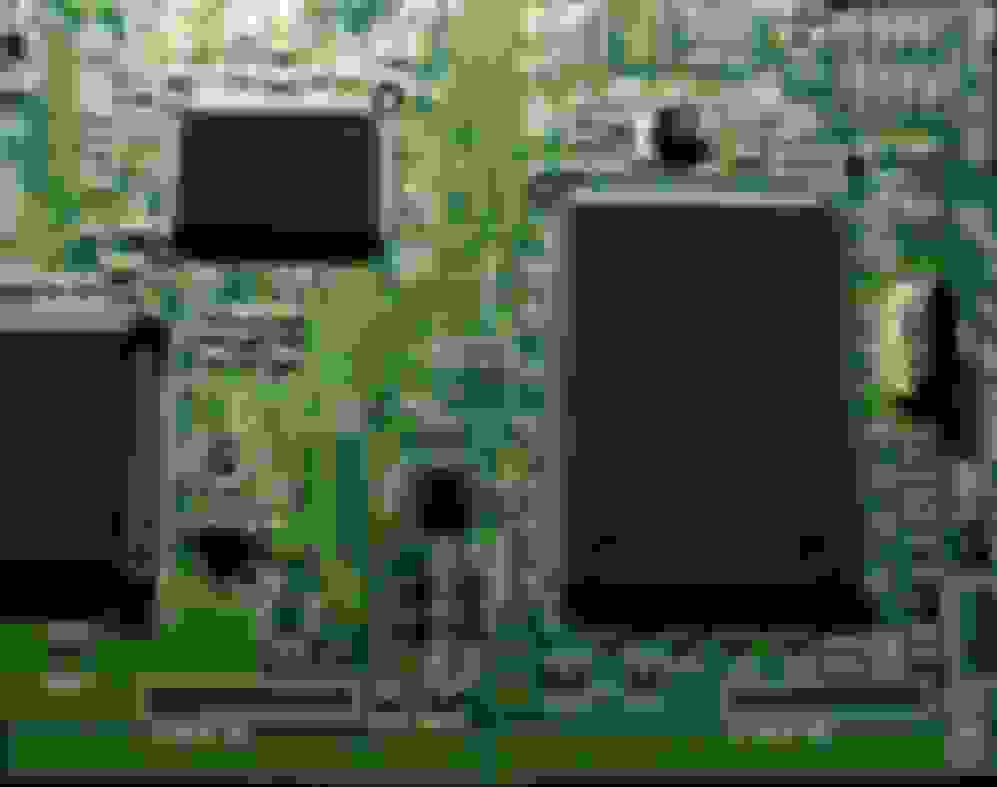
S1 ECU has nice easy screws to extract the PCB off the metallic case. S2 ECU (CX-7, Mazdaspeed3) has a composite case that is glued on with silastic and you have to tactically pry it off with enough force you'll be scared of breaking something important(TM). Once off, you'll have this in front of you - or at least, the important bits.
Like most boards, there's an area for power and filtering, I/O enhancement, etc - but the heart of the board is the SH7055 there on the right. On the left (and partially cropped out) is the microcontroller that drives the throttlebody - it's a separate unit, because if you remember the runaway toyota debacle (though not directly responsible), it's generally a good idea to keep the throttle controller apart from the engine computer. In the middle there is IC420 (yo) is labelled S-93C56C - which we can hunt down and find a datasheet for which reveals it to be an ABLIC 3 wire serial eeprom (SPI), 2k (2048) in size.
I'm not the best photographer in the world - but you'll probably note how clean and shiny the board is, and how hard it is to see the stamps on the IC's. Well that's because the board is covered in conformal coating - which is basically a really thin veneer to prevent corrosion. Thankfully, it's not an epoxy-based coating which some manufacturers use, and can be wiped away with some acetone and q-tips. This comes in handy later when tracing pins.
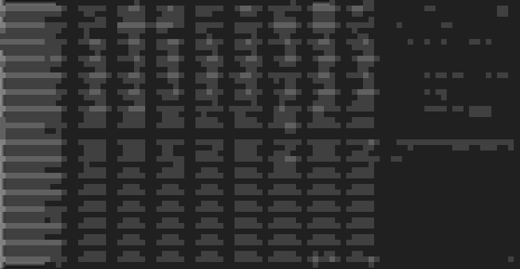
If we hookup an arduino to IC420, write a little bit of code, we can walk the rom and pull the data from it. This is what we get from the dump -
and that's repeated 8 times all the way to 0x7FF (2k). I haven't identified all of this data - but VIN is pretty obvious at 0x80, there's also the AsBuiltData (ABD) stored without it's checksums in there as well, though I'm afraid I didn't mark it in my notes the exact position.
Moving on - CN430 header is located there on the bottom right. Just in case the images get deleted in 5 years time, I'll describe this in text -
Silkscreen triangle on one edge, typical of many electronics, denotes pin 1. 13 pins long. This is the AUD interface - Advanced User Debugger in Hitachi/Renesas. Full credit to JamieM https://www.rx8ownersclub.co.uk/foru...=7129&start=75 for figuring this out, and also figuring out some of the ABD data manipulation (I'll get to this a bit later) working with FORScan as well.
geekspeak incoming - AUD interface is basically a nibble shift register. Clock in a half byte, clock in another half, MD sets mode (read/write), and then you can start clocking out data from the start address you've written to. AUD is a terrible to google for, basically, you always end up finding AUDio equipment or AUDio hacks - but I did manage to find someone who had written a AUD interface for the (oooollllldddd) Propeller microcontrollers, and then Daniel Hankewycz on a Volvo S40 wrote it for arduino - which I took as a basis and expanded a bit with a python wrapper to pull data out. With this I got a full dump of my bench ECU. (Again, I will release code, just gimme a chance to make it look not halfass).
Now AUD is only half the battle - despite being a read/write interface, you can't actually write to the ROM with it. You can make changes to RAM, but not ROM.
CN400 - Thanks to someone I don't know if I should mention, I got confirmation that this is the SCI (serial communcation) header for the FDT (Flash Development Toolkit). Similarly, 13 pins, Triangle denotes pin 1.
This is the unbricking interface. Those of you who know Toyota/Subaru will be aware of the SHBootMode method of unbricking a badly flashed ROM. This post is already lengthy, but FDT flashing / SHBooting will need it's own post. While I was researching I saw some people had speculated what Japanese Tune Houses were doing by looking at grainy video screenshots - well, this is it. I wish Seikx8 and Oltmann were still around because the real fun stuff of reverse engineering the software side, they were clearly ahead of their time, but just didn't have the ability to put the bits back in.
Last edited by gooflophaze; 03-14-2021 at 12:09 AM.
A lot of great information in your post! Thank you for sharing that!
I'm newb so I'm afraid my replies are still under moderation and delayed - trust me, we're just barely scratching the surface so far. Still need to cover unbrick flashing, difference between obdii and canbus, difference between canbus and UDS, canbus dumps, how mazda is very much like subaru, how mazda is pretty much ford, bootloaders, why you can't flash with an elm327, fun with memory manipulation, and ghidra. Edit: this post put me over the newb threshold?, so now gotta wait for last nights post to be approved...
Last edited by gooflophaze; 03-12-2021 at 06:18 AM.
Thank you for taking the time to examine this and to post it. One thing I have wanted on this car is a functional coolant gauge. Based on previous posts, the controlling algorithm for the gauge is onboard the gauge cluster itself. That may or may not be correct. If someone could implement a usable coolant gauge, I would pay for it. I am tired of looking at an instrument cluster that has two useless gauges staring at me. (oil,coolant). The temp info seems to be available to the gauge, it is just factory set up to be non-linear. The oil pressure gauge would require a sensor change also, since it is just a switch. Maybe will be possible later. If you can help with this, I am sure there would be others who would like this kind of modification. It is difficult on this car to get accurate coolant info for an aftermarket gauge, because of where you have to locate the sensor. All the known locations are compromised in some way as far as accuracy. So, please, if you have time, I would love to see you explore this. Thank you.
Last edited by kevink0000; 03-12-2021 at 08:28 AM.
The short answer for the IDC is... run a 52mm gauge pod. The longer answer is that's a different piece of software, different hardware. It's reading the raw canbus values broadcast by the ECU to controller stepper hardware. Basically like the ye olde teddy ruxpin's, the mouth is moving because of the volume of the cassette tape. We haven't even gotten into ghidra and SRE, and I can assure you, it's already a pain to interpret the software, much less write meaningful functional changes to it. Tables? Those are ez. Moving the needles differently? Waaaaay harder.
Thank you for taking the time to examine this and to post it. One thing I have wanted on this car is a functional coolant gauge. Based on previous posts, the controlling algorithm for the gauge is onboard the gauge cluster itself. That may or may not be correct. If someone could implement a usable coolant gauge, I would pay for it. I am tired of looking at an instrument cluster that has two useless gauges staring at me. (oil,coolant). The temp info seems to be available to the gauge, it is just factory set up to be non-linear. The oil pressure gauge would require a sensor change also, since it is just a switch. Maybe will be possible later. If you can help with this, I am sure there would be others who would like this kind of modification. It is difficult on this car to get accurate coolant info for an aftermarket gauge, because of where you have to locate the sensor. All the known locations are compromised in some way as far as accuracy. So, please, if you have time, I would love to see you explore this. Thank you.
I just got an OBDLink MX. I'm fooling around with it today to see just how accurate/granular the various data is.... coolant temp, oil temp, etc - and how they correlate (or don't) with the dash gauges
The ECU data is accurate - however, the oil pressure is a single bit. on or off (0x01, 0x00). Switch-type sensor with a 10psi threshold. The IDC coolant is Low / Medium / High (0x40, 0x80, 0xC0). The only inaccurate bit about the coolant gauge is that it has a very slow swing time - from low to high takes about 15 seconds. At least the oil pressure isn't simulated like it is in the NC - which has the same switch setup, but the oil pressure gauge wiggles with RPM and Coolant temperature.
OBDII was defined by the SAE as a method to unify various scanners (each one being manufacturer specific) as well as allow provide a way to monitor cat efficiency to simplify emissions monitoring. In 1996 all cars were made OBDII compliant (in the US - few other countries have different dates). Instead of making every OEM reengineer their entire communication system and tools, they allowed multiple interfaces in a single J1962 plug - https://en.wikipedia.org/wiki/On-boa...stic_connector .
Most of these are some variation of just a simple serial protocol, and very, very, very slow. 10,400 baud (bits per second, roughly) for K-Line and VPW (J1850), most were serial-port based. Fine for pulling diagnostics codes when the previous method was reading 'blink codes', but advanced they were not. CANBus (Controlled Access Network) however was different - 500,000 baud rate on a differential signal pair that took some elements of ethernet networking with collision control and priority messaging, along with some elements of RS485 which is a serial protocol used for industrial controls. Cars are *very* noisy electrically and have some unique challenges with signal integrity and I could speak for more paragraphs about the beauty of differential signalling - but that doesn't bring is back to the point of the difference between canbus and OBDII.
CANbus is the superior protocol - and as of 2008, all cars were 'forced' to adhere to this standard (this wasn't done overnight - similarly to 1996's OBDII standard, it was defined and announced years prior). But the thing I want to emphasize is that OBDII is not Canbus. Canbus is the telephone line, OBDII is the conversation.
OBDII scanners have circuitry to talk (with varying levels of success) to all the OBDII protocols - and they can request information / codes / current engine status / error frame data in somewhat the same way. So when you're using a cheap $2 ELM327 based knockoff in your 98 Ford, it's speaking OBDII using VPW to clear the misfire code. Same ELM327 in your RX8, it's using Canbus to speak OBDII to clear the cat inefficiency code.
OBDII is a request/respond protocol - nothing is 'speaking' OBDII by default. If you use the android app Torque with your ELM327, it's saying "hey ELM, ask the ECU what the rpm is?" and it asks, and the ELM gets the response, and sends that to your phone, and your phone displays "2112 RPM". OBDII is also limited in that regards - It can only ask for things that are 'defined' by the OBDII spec - https://en.wikipedia.org/wiki/OBD-II_PIDs shows the list of them. If you'll notice, there's a few things that would be handy that aren't there - like oil pressure. On vehicles (that have analog input oil pressure sensors) these are typically available via "enhanced" diagnostics, also known as mode 22 (though it's not always mode 22) requests. These are available PID's that manufacturers / licensed by manufacturer scanners can read (think Snap-On, MacTools). These mode 22 PID's are often available for Torque to be input manually, but there's no 'unified spec' on how to interpret the data like there is standard OBDII pids.
I suspect this would be as good a time as any to show what an OBDII request looks like - Note that spaces are added to make things clear. 7E0 is the "Scanner" requesting data. The responder (MUT, Machine Under Test) adds 0x40 to indicate it's a response to this query.
Code:
7E0#02 09 02 0000000000 - 2 bytes being sent - mode 9 (request vehicle information) - VIN number request
7E8#10 14 49 02 01 4A4D31 - 10 part 1 of a multi part response - 14 bytes long - 49 (response to VIN, 0x40 + 0x09) - something something - 0x4A.utf8 = J, 0x4D=M, 0x31=1
7E0#30 00000000000000 - acknowledgement from scanner this is a long message, continue, I'm listening
7E8#21 46453132333435 - 21 - part 2 of long message, 0x46=N, 0x45=E, 0x31=1, 0x32=2
7E8#22 36373939393939 - 22 - part 3 of long message etc etc etc
If your eyes aren't crossed yet, you might touch computers for a living.
With the rise of computers in cars, though, canbus proved to be valuable way for different modules to share information - for good or ill. With the RX8 ecu on the bench, sitting alone with no other modules, this is what a single second of data looks like - and the first column is the number of times that data was sent.
So.. we have Canbus and OBDII - now it's time to enter the next protocol, UDS, or unified diagnostic services. UDS is yet another SAE standard - why standard? Because a long time ago, some people believed the right to repair, which meant you couldn't shut out independent shops / force them to buy vendor specific tools. OBDII is fine for running by autozone and checking what a code is, but UDS is meant for software updates of modules. This post is already running long so I won't go into detail here because it's gonna be a long one when I cover reading the firmware through canbus and this is just meant to be a primer.
During the 90's and 00's, Ford and Mazda had a strategic alliance, and as such, Mazda used a lot of Ford technology for enhanced diagnostics - and thankfully, though not always explored, the excellent software FORscan, which is primarily designed for doing vendor-ish specific jobs like resetting immobilizers and authorizing keys, works with Mazda - and it can use (though not always 100% because the cheap ELM327's have some technical limitations) relatively inexpensive diagnostics cables. However, for heavy lifting, J2534 is another standard - this one calls out how your computer talks with your scanner device that talks to your canbus network that talks to your ECU. J2534 allows end users (and independent repair shops) to perform their own software flashes. As we said before, canbus runs at 500,000bps - if you work in technology, you know that many devices are (often) a paltry 9,600 baud, or 115,200 if it's "high speed" serial. Canbus needs a bit more 'umph' to work with serial - and that's where we hit some limitations of the ELM327. Since many are backed with a (very very cheap) bluetooth serial connection, it's not feasible to do any real 'heavy lifting' with them. Even the OBDLink products, which are basically very fancy ELM327 devices that are wired, are limited because they are not true J2534 devices. And for those confused "well they read canbus at 500kbp, why can't they?" it's because they filter out data. They only pass along OBDII responses - data sent on 0x7E8 - across the serial link, and ignore the rest, so they're not overwhelmed with data.
alright, that's enough for this small essay..
Last edited by gooflophaze; 03-14-2021 at 01:19 AM.
Hey gooflophaze, happen to have any more info on the AUD interface you built?
I'm currently decompiling a rom dump from an 06 Shinka, and am at the stage where a live snapshot of RAM would be helpful.
The work is being done in Ghidra, with HEW as a simulation platform. There's some heavy leaning on info from the RomRaider forum, as well as some other random tidbits around the web.
The main bugbear I'm having is that without proper emulation of all the peripherals, the simulation falls flat waiting for ADC conversions, DMA transfers, interrupts that never come in, etc.
Goals are getting an active exhaust system installed and handled native by the ECU (Think 3000GT VR-4 sport/quiet mode), possibly boost control for a Frankenstein's Monster style tubeframe project, and some other random stuff to get an engine running without the rest of the car attached.
It's also a project to keep me from going nuts when 06:00 and 18:00 are both darker than heck...
Eventually I'm hoping to get things cleaned up enough to drop on github or similar.
Been enjoying this thread, thanks all! Any further update? My short term goal is to run the renesis on an engine stand on the stock ecu without the immobilizer module.
I've walked this path in the past and found it to be 99% a dead end with no scope of improvement or 1% a wasted effort to find nothing of particular interest.
I do have some spare ecus, a tactrix 2.0 cable, mazdaedit, forscan, debuggers, all the spare time to kill during a pandemic lockdown... and came up empty handed.
Trying to reverse engineer the stock ecu to the point that it can be reflashed with a free open source tool is, by now, useful to very few people. You still need a rather expensive tactrix cable or equivalent obdlink one. After that it becomes a futile scope of importing maps from Versatune or ME into this new tool. Sadly I do not see any gain in doing what I see here.
About those coolant/oil gauges I have done plenty of research and came up with the findings that the coolant one can be fudged to show some more meaningful values without any extra hardware. There is a table buried up in the .hex of mazdaedit, not gonna disclose its position as my findings are anecdotal at best and NOT repeatable across ECU SW numbers. Also some erratic movement was spotted which at times resulted in a stuck needle - so I'm not even close to making it work half decent and i've since given up.
The oil side is even more of a lost cause - firstly the hardware to grab true oil pressure is missing. Secondly, the fw in the cluster does not allow some sort of PWM'ing of the bit to make the needle sit somewhere in the middle. Thirdly the MCU pin to which the factory oil pressure switch is not an ADC input, only a digital one - but I might have read the DS wrong. So no shot at using some resistive sensor and altering the FW in assembler instructions...
Sidestep: the BARO sensor scaling can be changed, but it leads to absolutely horrific results. I was hoping to create some sort of boost enrichment during NA to boost transition. Just goes to show that OEM ecus are good for passing emissions and not much else.
I hit a snag in diving into the next bit - trying to describe the authentication process for gaining access to the ECU and perform a dump. There are carve outs for security researchers, but right to repair doesn't currently have those provisions, so after pinging a few of my security friends to see if there was a kosher way to release my code I stalled out - then a bunch of life stuff happened - so I wasn't able to get around to it. The process is already described (and coded) by another security researcher, but incorporating their code into my code is a gray area.
 03-11-2021, 05:36 PM