When you click on links to various merchants on this site and make a purchase, this can result in this site earning a commission. Affiliate programs and affiliations include, but are not limited to, the eBay Partner Network.
My curiosity comes from wanting to do an LFX build through Keisler. Although a lighter engine compared to the 2jz, it is known you lose the sharpness of turn in by going to an LFX, and was curious about taking it even further with the 2JZ which appears heavier and more forward mounted.
Pictures don't do any justice but the lfx sits past the lower cradle/rack, but I can't say how much less than the jz. I'd say the jz crank pulley is about 4-6 inches past the rack
I think the weight difference definitely would be the real factor. If the lfx has turn in issues then the jz definitely would have some lol.
You guys know a lot more about this lane of things than I do but would the monstrous sway bar that Keisler offers make any difference in that aspect? I have it for my swap to clear the motor but it also gives you much greater inner wheel clearance which is great for drifting or hot boi wheel fitment. It's a key reason I can run 10.5 +12 up front
As you can see it's stock twins which I would tell anyone is a complete waste of time. They fit with minimal modifications but clutter the bay drastically. The main issue is the heat they hold. I don't have any issues with overheating or anything but under hood temps arnt the best. I've since revamped all my cooling situation to regain AC because I live in texas... I'll post how I did/doing that in a few First time out the driveway under its own power back in 21 Engine, trans and diff carrier mounts are one off. I'll take better pictures so you can get a better understanding. The transmission mount sits on a chassis brace we made utilizing the factory brace bolt holes
Spoiler
It looks so beautiful. <3
Last edited by HeidePhillips; 05-18-2023 at 05:54 PM.
I've got nothing whatsoever against rotary motors and actually have an fc vert I'm restoring. My jz setup sat on a pallet in my garage since 2011. Life got in the way so trust me bro I feel you putting life before hobbies. Whenever you get things lined out and underway hit me up man I'll share what I can to get you on the road
Yeah, keep posting updates, please. The wife is wondering when will I ever start. I just was able to get the engine before the price hike and told her, "Not at the top of my list, but I will get parts very slowly. Why tear the engine out when it's still healthy at the moment?"
Yeah, keep posting updates, please. The wife is wondering when will I ever start. I just was able to get the engine before the price hike and told her, "Not at the top of my list, but I will get parts very slowly. Why tear the engine out when it's still healthy at the moment?"
Timing is everything trust me. Being in a rush or just simply not having a plan has caused me more frustration in life than anything else lol.
Anywho updates for now. Got things buttoned up with some new issues to solve lol. Dbw seems to be temperamental on me.
Added a 3 port sealed catch can routed to the intake. After countless debate threads on the supposed correct way to do this, this seems to be the most agreed upon method and I don't get the fumes in the cabin.
AC is physically connected but I haven't driven the car to the shop to charge it up. I'm trying to make sense of the wiring but the few solutions I've come across are a little confusing in their explanations. I saw Stubbs thread on how he did his but I'm not quite getting his diagram lol. I can run it through my standalone but I'm out of inputs so I'd have to change to many things around. Also the JZ compressor has a compressor lock switch which I haven't quite understood what it does or how I need to wire it.
Also discovered by removing the Mazda ECU entirely, I had to go back and ground the starter relay to get signal to the solenoid. Im using the X19 plug from the fuse box to engage the starter. I've looked through the fsm for my model but I can't quite find the diagram for that plug and what the other wires do exactly. It's from the charging system short harness.
Alrighty, got a very helpful PM back from Stubbs and his blessings to share it.
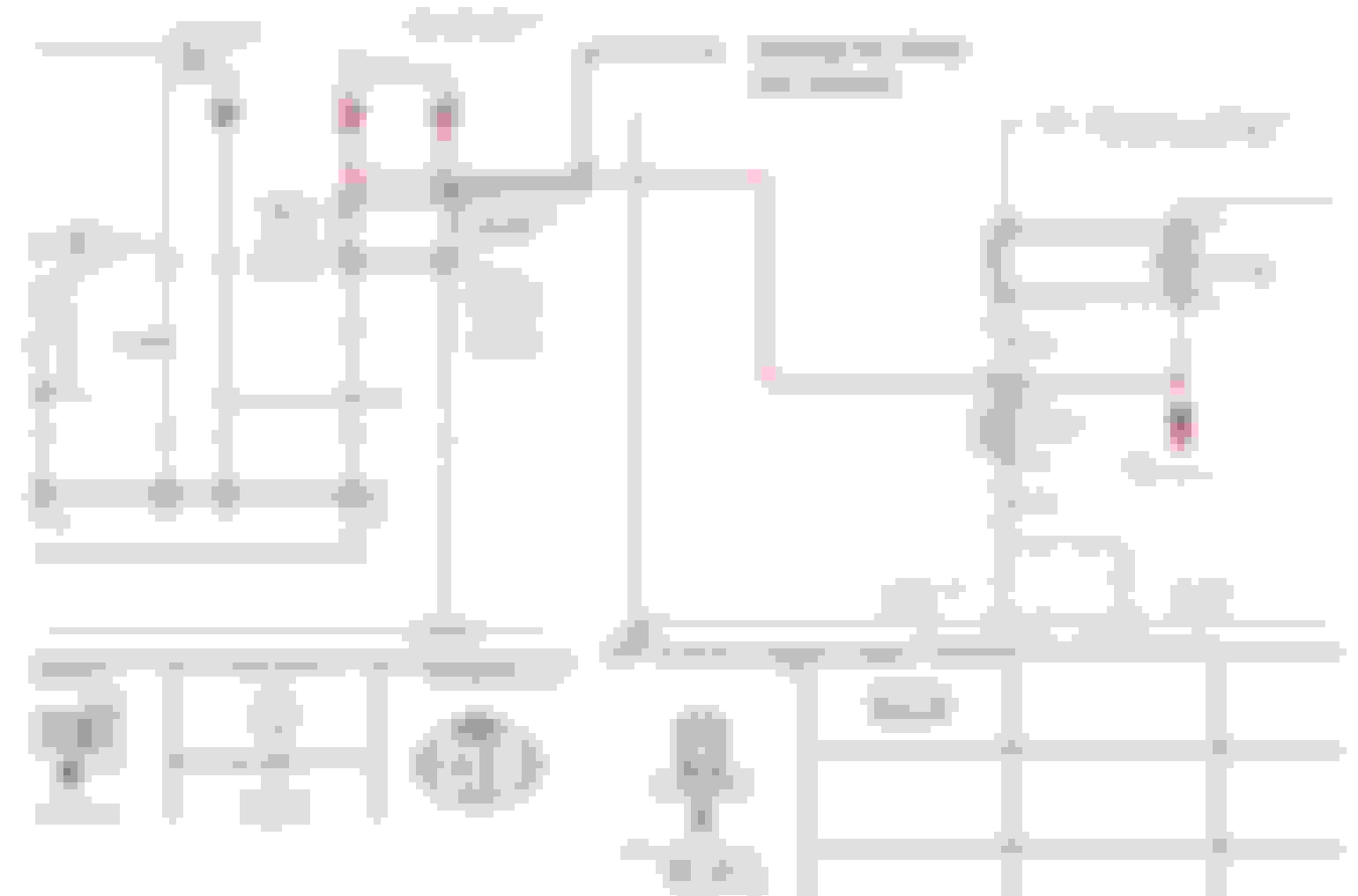
Here's a brief description of how the AC works in stock configuration: Press AC button --> AC amplifier(AC control module) sends a ground to the the refrigerant pressure high/low switch --> if the AC system pressure is between 30 to 450psi the refrigerant pressure switch is closed allowing the ground signal to reach the ECU --> the ECU receives the AC request signal and compares the request against operating conditions (below certain RPM, coolant below a certain temp, etc..) --> If conditions are correct ECU sends a ground signal to the green/black wire on the AC relay which closes the contacts and sends power to the AC Compressor Clutch turning it on. Similar thing is happening with the cooling fan control.
I reused the stock Mazda switch and connector, but the wiring will be the same for any trinary switch. For the compressor control: The Red/White wire from terminal 1M on the AC amp goes to the refrigerant pressure switch(trinary switch) High/Low switch, then out to the Green/Black wire on the AC compressor relay. Black/Yellow on the AC compressor relay goes to the compressor clutch. For fan control: The Red/Black wire on one side of the Medium pressure switch goes to the coil on the fan relay. Depending on how your fan control relays are setup (ground activated or 12V activated)use a ground or fused 12v on the other side.
I have an s2 and the wire LG/B is instead LG/R, otherwise the rest is the same.
Wire colors are not important but pins are. This fuse block plug feeds the starter signal on top left and ac clutch signal bottom left(Toyota compressor plug)
Added a 3 port sealed catch can routed to the intake. After countless debate threads on the supposed correct way to do this, this seems to be the most agreed upon method and I don't get the fumes in the cabin.
A bunch of questions incoming as I'm trying to figure out what to do with my setup-
- What are the ports on the valve cover (do they have different purposes)?
- Is there a PCV valve?
- What is the expected flow path?
- Is there a check valve that closes under boost?
A bunch of questions incoming as I'm trying to figure out what to do with my setup-
- What are the ports on the valve cover (do they have different purposes)?
- Is there a PCV valve?
- What is the expected flow path?
- Is there a check valve that closes under boost?
I'll answer as best I can. So in my picture I actually hooked it up wrong, (too many beers) but since corrected.
So on jz motors the pcv valve doesn't do much and like all pcv valves, closes under positive pressure. Originally it ran from the intake manifold into the fitting on the driver side valve cover. In between the valve covers are crossover tubes that during positive crank pressure would flow into the passenger valve cover and out the fitting in that side and directly into the turbo inlet tract. This is all well and good emissions wise but obviously outs alot of oil in your system. My intercooler was holding like 1/4 qt of oil when I took everything apart along with my lower intake runners. Now the majority of this oil is from my clapped out OEM turbos on their last leg.
Under much higher boost loads on larger frame turbos JZ motors have had issues blowing out front main seals. Most guys just run a 10an setup to a vented catch can which I was running originally. I went to this 3 port which has two inlets, one for each valve cover for the best possible flow and one filtered outlet that's ran to my intake. This way I'm removing as much crankcase pressure as I can which will help old seals and gaskets not leak under boost also. The catch can itself is sealed.
Radium makes those press in ports which are very expensive but convenient because you don't have to weld anything nor even remove your valve covers. They swivel so they can accommodate any arrangement for your hoses.
In truth this could be overkill idk but that's just how I like to do things because "in theory" I'll never have to worry about it. Also it pleases my inner ricer to have more AN lines and fittings lol.
Had a chance to look through you posts about your engine swap. I really like your car. I'm also interested in your new turbo upgrade. Looks like it's going to be a clean installation. Thanks for sharing your efforts.
Had a chance to look through you posts about your engine swap. I really like your car. I'm also interested in your new turbo upgrade. Looks like it's going to be a clean installation. Thanks for sharing your efforts.
Thanks man! I've been doing everything I can to make it clean and minimal because the clutter was driving me crazy. I knew going single would solve numerous issues I had. If you have any questions I'm more than happy to share what I know 👍
Pulled the trigger on paint work. Yanked the engine to paint the bay while I repair the rest of the exterior. Still waiting on parts from japan to finally arrive Doing seal and belt maintenance while its out
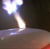
Not the prettiest thing and i dont claim to be a welder, but for mig welded stainless im satisfied. Went with the wire tied method as i seriously hate those metal zipties Wrapped the downpipe.
How much more underhood clearance do you think that hood gets you? I'm in need of a little more room and I've been eyeing hoods like that.
So the area where your hood insulation goes has more clearance on the front edge of it which is exactly what I needed because my coil pack cover, radiator cap and throttle body where digging holes in mine. I've cncd a real adapter for my throttle so that's moved it closer to the manifold which should help also.
I haven't actually mounted the hood yet but I'd say it's definitely got atleast 1/2-5/8 more clearance from the oem underhood webbing. And the gossip is true on the weight, it's not lighter than the oem. However weight was never the concern.
Tons of fun removing the spray paint from the bay. Oem paint is very weak/cheap and comes off also with the slightest hint of thinner. Applied POR to some light rust spots. Hopefully I can get the bay painted this week.
Woah!!! Your car is seriously going to be next level. Nice job on the rear quarters too. Are you adding rivet nuts for the rear flares and or side skirts? That's what I had done and imo is a good idea for service / longevity.
Kudos on all the quality work. Great thread. Can't wait to see it completed.
definitely going with riv nuts with the rubber seals like the ones downstar offers. I leanred my lesson on regular rivets on my brothers 240 which has since been cinverted also to riv nuts.
Side skirts I'm still running the oem r3 skirts and will probably add some splitters to them.
I'm trying like hell to get this thing done but it's like work keeps multiplying because I can't live with certain things or the OG guys at the shop press me to go further lol.
 02-20-2023, 12:24 PM