When you click on links to various merchants on this site and make a purchase, this can result in this site earning a commission. Affiliate programs and affiliations include, but are not limited to, the eBay Partner Network.
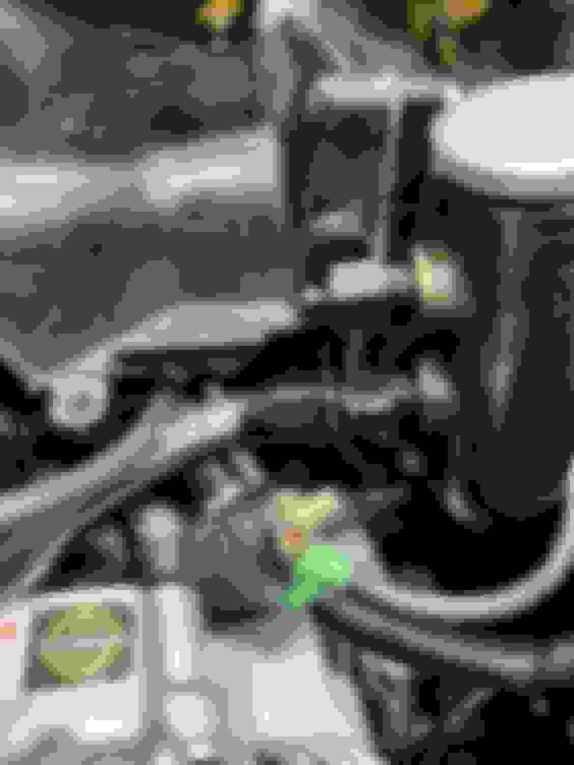
Also, since this seems to be asked a lot by guys looking into REW swaps and banging out the firewall. Here is the factory LIM held up and lined up with the bolt holes of the Xcessive. The latter nets you about 1/2" or more of additional firewall clearance.
Its not just he lateral clearance, the stock lim is squared off on the edge facing the outside of the intake. I had tried to shave that off and still needed a lot of hammering to fit.
Engine back in the car. A few additional photos of some of the clearance I have at various tight places. Note with the weight of the front of the car on jack stands I don't have the full weight on my rear wheels either. This causes the tail of the transmission to drop a bit tilting the engine back towards the fire wall. When I drop the car back to the ground I will have roughly ~1/2" more clearance and firewall and a tighter clearance between the subframe and turbo compressor. Also my secondary fuel rail sits further forward obviously now too. Noticed when connecting the fuel supply to my primary rail that the gauge port body of my AN fitting makes contact with the secondary fuel rail spacer. Was still able to get this threaded on and buttoned up but will be keeping a close eye on this to ensure there not pressure on the secondary rail which could cause and issues with injector seating/leaks. I think unlikely but noting it anyways. The old positioning this spacer fell right in between the two pressure senders. All-in-all, everything went pretty smooth and it's just a matter of bolt-up, harness, fluids before I'm ready to fire it up. Will be making one or two minor changes (need a new coolant cap flange on my swirl pot that I'll have a friend weld for me) as well.
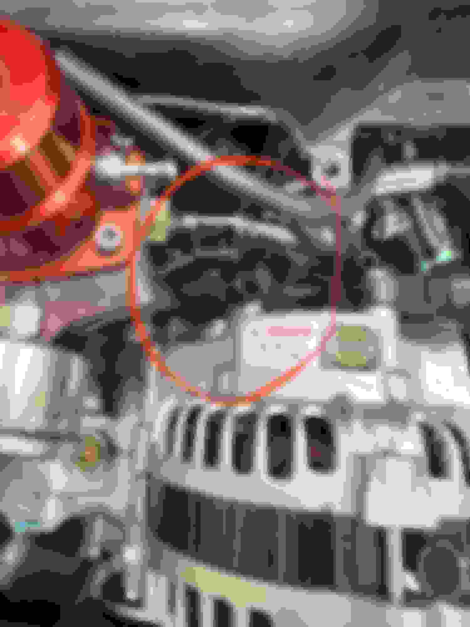
Engine in. Compressor to subframe, will move slightly forward when I drop the car down. Gap between compressor and LIM Firewall gap now with Xcessive. For reference, in this position the stock LIM rear stud would make contact with firewall. This gap will get a bit larger when car is put back on the ground. Secondary fuel rail spacer making contact with AN fitting for fuel pressure sender. Clearance around clutch slave and oil pedestal adapter. Looks tighter than it is, all hoses and lines have free movement in that area.
Xcessive vs Stock LIM against firewall for comparison. I didn't think this LIM was going to net me that much more clearance, but now that I see this in person this is almost a must for swapping! I haven't tried yet but I used to to have to squeeze my hand under UIM above fuel rails with a short stubby wrench to get on that rear nut. Now I think with UIM on I'll be able to get on it from above with a socket and U-joint extension.
Some big wins last night along with a few "still needs work" items. Mocked up the UIM and everything else around it loosely to identify any interferences due to the xcessive vs stock LIM position.
Oil fill neck fits but the AN fittings I have installed on it for venting are pretty tight to the UIM (particularly the vacuum lines off the front). This will work as is but likely I'll look at getting the flange on this clocked a bit so it sits tigher to the intake elbow and leaves more room for the vent lines.
Rear nut on the UIM is now nicely accessible from the top of the engine with a socket/swivel extension, no more reaching in between fuel rail and UIM to get on this one.
Minor, but my fuel supply line from secondary rail to regulator is hovering just above the alternator right now. This may or may not contact alternator when I raise it to tension the belt. Hoping I can just rotate this fitting enough so it falls behind alternator. If not I'll look at a new short braided line for this where I can connect to the other side of the regulator.
Charge piping to the throttle body no longer fits. Was hoping there was enough play in this to be direct fit but the fix is simple. Below the coupler on the charge pipe from intercooler outlet, I can shorten that section, re-bead it, and it should mate up. It's not that the TB sits any lower now, its just more forward; to move that coupler between the two piping sections forward I had to also bring it upwards more, there was plenty of play in this section, but now it's just slightly too long.
While I'm getting some of these minor tid-bits addressed I'll pull this all back apart, run my wiring harness and connect everything, then put it all back together for good. :D
Last edited by RotaryMachineRx; 06-08-2023 at 12:55 PM.
Harness is in. All of the interferences are taken care of. I have a few bolt-ons, belts, air filter, etc to put back into the engine bay then it's ready for fluids. Planning to do first start this Wednesday
First start! Will do another full heat cycle on the stands, make sure I have all the coolant air burped out. Likely will compression test for a baseline then take it for a 50km or so drive then change the oil. Once I've done this I will carry on with engine break-in (I will be doing significantly less than I have in the past for this) and tuning.
Took baseline compression test. This is with the engine piping hot. This is after about 1hr of total run/idle time on this engine only, still 0 miles. It's ready to get back on the ground and start some break-in now! My experience these comp numbers will come up fairly significantly as the engine breaks in, but most importantly in gauging my engine build is to note the consistency of the faces on each rotor. Real happy with these numbers.
Here's another video of the car warm idling just for fun:
Tuned up to 11psi last night (link for video below). Seems to be pulling well but EGT's are a bit of a concern. There was a lot going on so I can't say exactly when I saw this but my gauge peak shows rear at 988C (1810F) and front at 915C (1680F). I'd say most time while I was watching during pulls I was seeing peaks around the 900-940C (1650F - 1740F). I've known my exhaust manifold may be a bit of a flawed design, we'll see if we can offset the rear/front temps with some more tuning. My exhaust is not helping either, I have all 3" exhaust but the flanges on the HKS catback and the BHR midpipe have 2.5" flanges on them; ideally I'd like to get these all cut off and replaced with 3" v-bands.
Other than the EGT issue mentioned above that I'm hoping to get some exhaust work done this winter to alleviate (if this doesn't do it then I'll need to fully reconsider my exhaust manifold), not much else to say. I'm seeing a bit of a strange fuelling issue on decel (going full rich) so I have a set of ID1050x injectors to replace my current ID1000 primaries to see if that solves the issue. If not i'm willing to point the finger at my Adaptronic ECU (I'm already looking ahead and seeing a new Haltech Elite in my future when it's financially viable). All the info from my data logs look to be solid during curise and WOT with some work yet to be done to transients and a few other characteristics to fine tune the car at 10psi of boost. I've been using Ryan Heinrich (RghtBrain Design) for tuning and I have to say the experience with him has been exceptionally good. Looking forward to making some changes over the winter and getting the car back on the road in the spring.
Here's likely my favorite picture of the car and how it sits as of today:
I forget, does the Adaptronic have a Oscilloscope included? You should be able to see what your injectors are doing on decel in the logs. I would have a hard time believing a swap of the injectors would fix that issue. If it were the injectors your car would be running rich, regardless. But I am speaking from understanding (I think ha) vs actual experience.
Yes Adaptronic/Eugene does have an oscilloscope....... something I need to learn to use haha. I'll definitely dig into that.
Although I agree, I haven't put any emphasis on the injectors prior to this as they have been cleaned and tested by two independent shops have have been returned back to me with reports showing they are in perfect condition. The reason im trying new injectors is because I think I've tried everything else I can! I'm not so much saying there is an issue with the injectors themselves, but maybe an issue with Adaptronic vs the ID1000's. I've talked to a couple of people who've seen similar conditions with ID1000's installed. Believe me when I say that doesn't hold much water in my opinion either, but I picked up new injectors on a black friday deal so figured it's worth a try at least.
Also just for an additional tidbit of information. I did swap in a different Adaptronic EMOD013 ECU to see if it was maybe just MY ECU, but the issue persisted across both ECU's. The only way I don't go full rich is if I put fuel cut on during decel; even then it goes full rich for roughly 0.5 to 1 seconds after throttle lift before going full lean as expected. Even with the delay in Eugene for decel set to only 250ms.
Correct, the primaries are the only injectors with any duty on decel. I've brought this up with Ryan and we've tried to address it. We even switched all my maps to custom injector settings as opposed to using the Adaptronic preset injector database. This helped at lower loads but still goes full rich above 4000rpm. So we've tried to address this via tuning with not much luck, switching to some 1050's was a suggestion from Ryan as it sounds like he's had good luck with them and the Adaptronic.... we'll see if it makes a difference I guess.
I don't think its a wideband issue, was seeing same thing on both my Adaptronic wideband as well as my independent AEM UEGO wideband. Not to mention the black smoke and flames shooting out the back of the tailpipe if fuel cut is not engaged, so it's definitely getting fuel on decel and not just a wideband error.
Is tuning perfected? Absolutely not, this is after only one session of tuning where we introduced boost to this engine for the first time, so there's definitely work to go, specifically with transients, but we have tried to fight with the decel fueling (on this engine and while we were tuning the previous engine).
I've attached a CSV file log (I use MLVHD to view my logs). Keep in mind this log is with fuel cut on during decel so you'll see it goes full rich immediately after throttle lift for 0.5 to 1s prior to going full lean as expected due to fuel cut.
Last edited by RotaryMachineRx; 12-15-2023 at 10:17 AM.
Also was trying to play with the Eugene scope.... I think this may only work with live data, wasn't able to get anything with log playback but maybe I'm not using it properly
So I essentially parked the car at the end of November and didn't even look at it through the winter. Kinda regretting that now that the taste of spring in slowly coming into the air; but I needed the break from it.
Anyways, I have some new ID1050X injectors I'm going to swap into my primary rail to replace my ID1000's. The hopes are that these will offer a bit better fueling control with the Adaptronic than the ID1000's seem to be giving.
During this process I decided to dive into my injector wiring just to see if I could find any obvious issues here. I have a few observations that I believe indicate I'm experiencing some sort of electrical issue in the car but this is where my inexperience with automotive electrical systems is really going to shine, so I have a few questions.
1. With the injector wiring, each injector connector my expectation is that there is one pin with 12V switched, and the other pin is wired to the ECU which grounds it to trigger the injector. I'm reading the 12V switched as expected when I ground the multimeter to my alternator body. When I measure voltage across the two pins of the injector connector I would expect to see 0V since the ECU should not be triggering the injectors while ignition is just switched to on, but what I'm actually seeing is 10V across my secondary's, and slightly lower ~9.6 V across each of my primary injector connectors. I'm not crazy, this is not right, correct? (Adaptronic ECU of course)
2. For fun I measured voltage between the ECU/ground pin of the injector connectors and the alternator body. When I click ignition on I read a voltage of 1.45V..... this then climbs as the key is left on at a rate of about 0.01v per second and I saw it get to about 4.5v. What is going on here and does this indicate any type of electrical issue? As an FYI I'm seeing this on another ground which is grounded to my chassis, when I remove the ring terminal from the chassis and measure voltage between it and its chassis ground point i see the same voltage rise over time (I don't recall what this ground was for but I have a friend coming over tonight to lend a hand so I can document this all better with photos/videos).
Anyways, hoping to get a bit of info from someone more experienced with this type of stuff than me to help with my diagnosis of the fouling plugs and over fueling I seem to be getting especially on decel. I'm certain the amount of carbon I'm seeing on my plugs is going to be detrimental to this engine in a short amount of time and hoping the excessive fueling can help explain the higher than normal EGT's I'm seeing.
When you say ECU grounded directly to battery, I can't say for sure. It was relocated to the trunk (obviously not by me) so I'll need to trace the actual negative terminal wire back to see if I'm missing anything more than this; but here's what I have on record when I was looking at this a bit in the past. Also I did test continuity from all of the power ground pins in my harness connector 5 and they all are continuous to chassis. All of my sensor grounds in that same connector are not continuous to chassis as expected. I have more info as follow up to my previous post that I will post up here a bit later, just getting my thoughts organized lol.
Last edited by RotaryMachineRx; 04-04-2024 at 11:04 AM.
Looking at the images I am assuming h2 is the ECU pin for ground and that it's connected to the common ground which appears to be a wire from the battery. I would first not have grounds underneath the car, that's just not the smartest move more likely to corrode. Also the grounds next to the exhaust is dumb. Also Also the transmission to chassis ground is not good, the engine mounts are painted and connected to the underside of the painted chassis. I doubt the engine and the chassis is probably grounded together.
The ECU should be grounded directly to the battery, one wire from the ECU connected directly to the negative post. The rest of the electrical system grounds can go straight to the chassis, common grounding would be best. The battery should ground straight to chassis with proper gauged wire.
I burnt up a Haltech Sprint RE way back in the day because of bad ground. Haltech has good documentation on their website as well.
Sorry, no H2 is housing 2. I have grounding strap between housing 1 and 2 on top of then engine, then run a strap from housing 2 down to that common chassis point. Paint is scraped off of the subframe where it is grounded.
This adaptonic PNP ECU, so I'm not sure how its grounded directly to battery; its using essentially stock harnesses with some mods for, air temp using the MAF wiring, and Rywire ignition harness pinned to connector rather than the stock coil wiring.
Last edited by RotaryMachineRx; 04-04-2024 at 12:15 PM.
I'm not sure what is there is worthwhile diagnosing and I would start over. The battery should be grounded directly to the chassis, the ECU ground you can pull out of the harness and run that wire directly to the battery. The engine should be ground directly to the chassis. I am suspicious that scraping off the paint is sufficient, it's not a good location for a ground irrespective, and it's not directly on the chassis its connected through a subframe and bolt.
Appreciate that feedback. When you say ground the ECU directly to the battery.... any idea which pin specifically? The Adaptronic Pinout has many power grounds from the chassis harness on both connectors 4 and 5. Pinout attached.
PS: anyone know where to buy a proper pin removal tool for the Rx8 harness connectors?
Last edited by RotaryMachineRx; 04-06-2024 at 03:18 PM.
Okay, so here’s the diagnosis I did the other night in regard to injector wiring:
1. Noticed primary injectors (secondaries don’t do this), are firing when I key on ignition (12v switched). I’m assuming this is a prime pulse but my understanding from Adaptronic (and HP academy) is that this should only pulse when RPM is detected (ie cranking). This explains the smell of raw fuel I get in my garage if I just key ignition on. With 50+ psi in the rails while fuel pump is priming this is likely dumping a fair amount of fuel into the engine, even when I’m not trying to start it. I’m not sure yet how this relates to the fuel dump we’re seeing on decel and throttle tip in/let-off or if this relates to the smell of raw fuel I get the next day in my garage after I park the car from driving (no fuel leaks anywhere). When I disconnect connector 5 from the Adaptronic the prime pulse with ignition key-on no longer happens. Also see my above video of the Eugene injector diagnostic tool and how it changes with connector 5 connected/disconnected to the ECU.
2. I’m seeing 12v switched to injector supply pin as expected. Strange thing I’m noticing: With ignition off I’m unexpectedly getting continuity on this pin to my chassis. When I switch 12v on continuity no longer picks up to chassis with multimeter. This is a stock rx8 harness with the connectors changed for ID injectors. Where does the stock rx8 feed 12v switched to injectors from? Wires are all in the main engine harness so does this come from the ECU? If so it’s not clear on the Adaptronic pinout where this is supplied from exactly (see post just prior to this for Pinout).
3. When I measure voltage from the ECU/grounding pin on my harness injector connector to chassis I’m seeing +1-2V across this. Under no circumstance do I see continuity from this pin to the chassis. No continuity like this is what I would expect to see since it should not be grounded because ECU should not be triggering the injector. I also tested this voltage on the ECU pin itself on the back of the Adaptronic and I’m seeing the +1-2V there too, so it’s not an issue with the harness injector wiring itself (these all have continuity through the harness). When I disconnect connector 5 from the ECU I read 0v on this pin at both the harness and the back of ECU which is what I feel I should see at all times regardless of connector 5?
4. When I measure voltage across harness injector connector I’m seeing 10v (I’m sure no coincidence this is the difference in voltage I’m seeing between the harness supply pin and harness ECU pin). Of course when I disconnect connector 5 from the ECU I then see 12V (12v - 0v) across these harness pins. Since the ECU should not be grounding to trigger the injector; should I not be expecting to see 0V here at all times??
Just some notes: for all the voltages measured above; whether I ground my multimeter to the chassis or to the alternator body; they are the same. I’m not sure yet how connector 5 relates to injectors; there is nothing in the Adaptronic pinout that jumps out at me.
I read essentially all the same voltages on all 4 injectors. I swapped in my new ID1050’s and they are also getting the prime pulse with Key-on, so I know it’s not an issue with the old ID1000’s themselves.
My harness itself is modified to add Rywire IGN1A ignition harness; my GM fast acting IAT temp sensor is wired to the associated factory MAF temperature wires, and I have a Hall effect sensor wired-in in place of the factory reluctor sensor (FFE trigger kit with 36-2-2-2 wheel). I’d need to do more digging to figure out the exact pinouts of these mods since I didn’t modify the harness myself when the initial swap was done.
With the above info….. I’m trying to figure out my next steps. With the amount of carbon I'm seeing at such low mileage intervals on spark plugs, out the exhaust and on my exhaust tip, and the amount of carbon buildup that was on my rotors when I tore the previous engine down after only 3000kms; a fueling issue seems to be obvious; I’m just not sure how to tie the above info all together with the issues we’re seeing while driving.
Last edited by RotaryMachineRx; 04-06-2024 at 03:36 PM.


 06-05-2023, 11:10 AM