When you click on links to various merchants on this site and make a purchase, this can result in this site earning a commission. Affiliate programs and affiliations include, but are not limited to, the eBay Partner Network.
Basically got the engine into the car to test fitment. I may take it out again since I do not have various gaskets and random bolts. Thinking of just buying JIS yellow zinc flanged bolts in bulk to start replacing old hardware. I already started modifying the UIM. The 3D scans are going well, I will have a manifold designed soon. Once I have most of the scans done I will make a google drive for them.
With the CX Racing crossmember and LIM the Nicon rotary oil pan sits fairly high. I assume it was designed around using the fd oil pan. To fit the Nicon pan, I will have to modify the crossmember's mount slightly. I have quite the wiggle room to play with in terms of manifold design.
Not looking forward to finding exhaust manifold gaskets, they are silly expensive. I am surprised a good aftermarket one is not available.
There are aftermarket exhaust manifold gaskets (they are one piece instead of two separate ones) and they are much cheaper, but from what I've heard is that the stock gaskets are far superior. Yes they are expensive but can be reused easily, especially if you think you'll have the manifold off and on a few times. In this chassis, let me tell you risking a leak on the manifold flange to the block is nightmare fuel lol
Otherwise, really looking forward to seeing what you come up with for manifold design!
Minc, IDK if you cut up your UIM yet, but I already cut mine in that location and will no longer need it. Plus the inlet is ported already. If you want, I'd be happy to figure out a swap/sell procedure. An unmolested one will likely sell better than one cut up for a REW swap.
Also which scanner are you using for your 3D scans? I've been meaning to scan mine. Maybe I'll try it quick tonight or tomorrow.
Also +1 for RotaryMachineRx gasket recommendation.
Sadly I have already modified it and ported the inlet.
The scanner is my brothers, i believe it is the einstar 3D. So far it is mind blowing how well it works. We should be printing a manifold tool this weekend. I should clock the turbo as well.
I plan on relocating the filter if I can. Ideally in the stock intake location above the crash bar. Mainly incase of rain or other fluids.
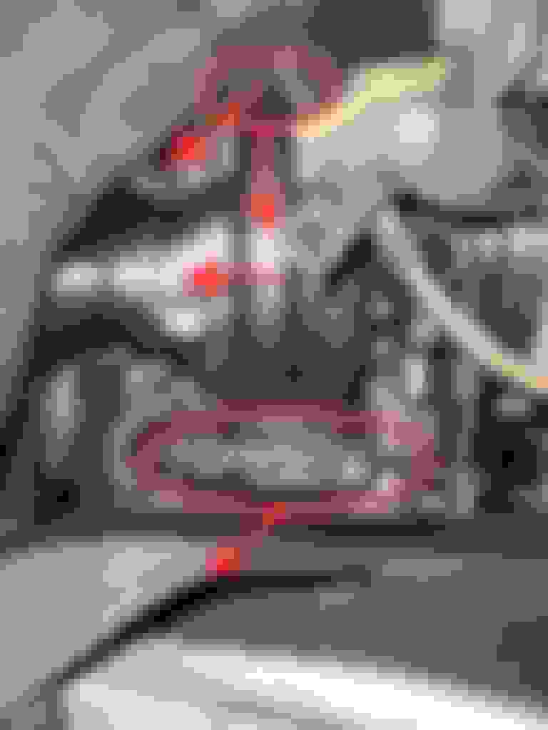
Already ran into my first snag. I got the JDL ac and alternator mount. However it looks like he designed it with his engine much much higher and my ac is conflicting with the steering joint.
I can see in your photos that I�m in trouble with a side alternator mount that I had been discussing with JDL. I�d end up with the same issue as your AC compressor, except I was wanting to relocate the alternator there instead. Will have to come back and review these latest posts later when I have more time.
The other issue on your setup that maybe you didn�t catch yet is the alternator placement is blocking the typical piping path from the intercooler outlet to the throttle body inlet when using the REW UIM.
.
If anyone wants close up visuals of those copper exhaust gaskets I can go grab them and check them out. I need one anyways. Its a benefit being local to Summit Racing ha.
Team, I got some help from Minc on the adapter and may be able to send you a 3D print that would be helpful for fitment if you'd like. I need probably a week to finish it though.
Those gaskets may be worth trying. Considering they are 10x less. Even if they are one time use, I dont imagine me taking the manifold off that many times. I have a lot of room to play around with the turbo.
One of my buddies 3d printed a mock manifold, hopefully we can test fit this weekend. He just picked up a 73' 240z with an L28 that should be cool to see.
I think I would have to already go around the alternator with this JDL bracket. Sadly it seems like I will have to move it up by about 1-2 inches. Which means I will definitely need to go around it charge plumbing wise. I almost wish the abs was in a different spot.
.
Before I start buying/wasting a lot on plumbing I am going to start making google docs for diagrams. I should be able to share them here allowing everyone to comment so I can make edits. These docs will be added to the first post of the thread.
fuel system with intank diagram (should have this started tonight, with some questions)
Alright the first iteration of my diagrams is ready to look at. Please see this LINK to my google sheets for the diagrams and a list of components. Anyone who uses this link should have the ability to view and comment.
Otherwise here is a pic of the current diagram, let me know if there are any scaling issues. The actual google sheet will have tables off to the side which list the actual components used. I also plan on making a table for all of the connections in the system which should hopefully ease the burden for buying AN fittings.
Looks Kosher to me, similar setup to mine (under the hood anyways) except I went with series plumbed fuel rails instead of parallel and I have my fuel pressure sensor pre-fuel rail. Both of these items are minor differences and shouldn't affect anything.
Well been out of commission due to health reasons again. I have been improving lately, so getting moving again. This will be a long post so please try not to quote.
The JDL surge tank is 90% the way there to going in. Just waiting on some simple things again. Honestly I can't say I am thrilled with his stuff, there are a lot of loose ends and unanswered design questions. Part of me thinks if I were to design said item and sell it, it would be better to offer a complete drop in ready to go unit. Clearly outlining -AN output and return, and including a wiring connector+plug to flying leads. I will include a post on this final assembly and install once I know everything internal to the tank fits.
The UIM is very close to the firewall. This may be partly due to the CX mount being too high. It was designed for the stock REW oil pan. I may redesign the mounting plate to lower and flatten out the pan.
+ + helping the UIM fitment.
- - not helping with the AC / alternator fitment.
The ExManifold designing is going well so far. Two revisions done, with the CX LIM I have a lot of room to play with for the turbo. Any suggestions on EGT sensors to use with the Adaptronic? I will want to include bung provisions on the manifold at some point.
Cad Mock ups, basically playing around with the flanges in space, then making splines to connect the outside faces. Effectively allowing us to begin angling the splines within the flanges. 1st revision 1st rev, symmetrical with about 30deg angle(too much angle) 1st rev hits the subframe, with tons of room towards the LIM. 1st rev has plenty of room in the front to play with. (note that this nylon printed turbo is not the IWG version which will move the T4 flange farther back by 20mm. Which will take up 20mm of room up front.) 2nd rev has about a 15deg angle. 2nd rev is asymmetrical making the front longer to move the turbo back slightly. This was due to the actual turbo's bov components. 2nd rev now clears the subframe. (if we lower the engine this may need to be addressed again. Likely the final rev will have parallel flanges.) 2nd rev The rear gap is about 10mm, but keep in mind that the IWG version of the turbo will be forward about another 20mm == 30mm gap. 2nd rev has more room up front, but makes us consider angling the turbo towards the nose of the car instead of being parallel with the E shaft. For now we are using a block of wood in the CX racing manifold since I did not get the proper engine mount bolts. (apparently mazda is now selling these again). Note that the nicon pan is thicker than stock, additionally I have a pan baffle plate also adding thickness. Rev 3 will try angling the turbo and adjust the flange angle for the new engine height. Only concern is that the front exhaust runner will end up being too harsh of an angle, closer to a 90>90deg instead of the symmetrical rev1 45>45deg angle. Or moving the T4 flange forwards in the car may be possible. The flow path of rev 3 will probably be one of these. I think the lower option may be possible if I get the compressor closer to the LIM which seems possible.
Engine Fitment and Hardware: You've successfully placed the engine into the car for test fitment. While you're considering removing it again due to missing gaskets and bolts, you're planning to replace old hardware with JIS yellow zinc flanged bolts purchased in bulk.
UIM Modification: You've begun modifying the UIM (Upper Intake Manifold), likely to accommodate the engine or other components.
3D Scans and Manifold Design: Your 3D scanning efforts are going well, and you're working towards designing a manifold. Once your scans are complete, you'll create a Google Drive to share them. I also recommend getting on the platform https://casinosanalyzer.com/online-c...rtunecoins.com which has a lot of information about different online casinos and more.
Oil Pan Modification: You've encountered a challenge with the Nicon rotary oil pan's fitment due to the CX Racing crossmember and LIM (Lower Intake Manifold). To make it fit, you'll need to adjust the crossmember's mount, and you have some flexibility in your manifold design.
Exhaust Manifold Gaskets: You anticipate difficulties finding reasonably priced exhaust manifold gaskets, and you're surprised that a good aftermarket option isn't available.
Glad to hear you are feeling better. Hopefully your health issues are over.
Wow those 3D printed manifolds are great. This helps me to visualize what mine will need to look like. I have been test fitting my turbo now that I have it and have found that the Nicon engine swap brace will require my manifold to angle downward as the turbo will need to sit an inch or so lower than yours. The distance from the engine and general angle is similar.
if I didn’t know better I’d think somebody leaked my manifold design to you.
might be able to help resolve the pinch angle if you want to email me. Hard to believe Turblown did theirs the way they did. It could have been better for sure.
.
MincVinyl what kind of gold tape did your use on your fire wall and was it difficult to install? Any recommendations for someone who is interested in doing that?
it was myself, anyone who paid close enough attention to my own explanations/words should have figured it out.
It’s perhaps easier to do and see in a 3D program; place a 13B exhaust port in one position, place the oval T4 port in another position, then determine the flow shape required to transition between the two. That in itself requires some thinking outside the usual box to manipulate the parameters and accomplish the goal effectively. Hats off to Minc, because he had already pretty much figured it out on his own.
Without a 3D printer though, it requires taking it to another level to get there manipulating pipe elbows and sheet/plate into an approximate welded equivalent. Whereas the 3D process accomplishes it more organically.
.
It was exactly that, placing two "flanges" in space and then making 3d splines going from the circular cross section output to the t4 rectangular input. Having a 3d scanner really helped so we could just put the engine in the car and rescan to get the exhaust port location. Then locate the turbo in the car's CAD model which gives the t4 flange location. Sadly I think the engine is a little off(high and angled), due to the conflict between the CX engine mount and the Nicon pan. We will have to rescan to account for this and then make another manifold prototype.
@Warrior777 I used the Pegasus gold heat reflective film. It applies like sheets of duct tape. You want to make sure the surface is completely clean of oil. On flat surfaces it is rather easy. The firewall was a lot of work, standing in the engine bay. Originally I attempted to do larger sections, but found smaller 6x6in or less sections to be easier. So this gold foil would just be the outer radiant layer and mostly for looks. At some point I would like to re-insulate the cabin with dynamat or similar product. Although there are a few people who did tests with Intake temps showing some nice improvements. How much will it help against cabin heat . I ordered a 2x7ft roll and still have like 2x2ft+ left for charge pipes or the lower intake tubes.
so here�s another way to look at it, not sure if you understood my message from a week or two ago.
you have to look back at how the Turblown manifold is placing the turbo, then resolve where it needs to go and how it�s positioned to fit. This demonstrates it well; it needs to move back to be centered to the engine exhaust ports, but it also needs to come down. When it comes down, this provides additional clearance to the intake manifold, which then allows angling the turbo back closer toward the engine as well. Then you get something more like this:
. . .
. .
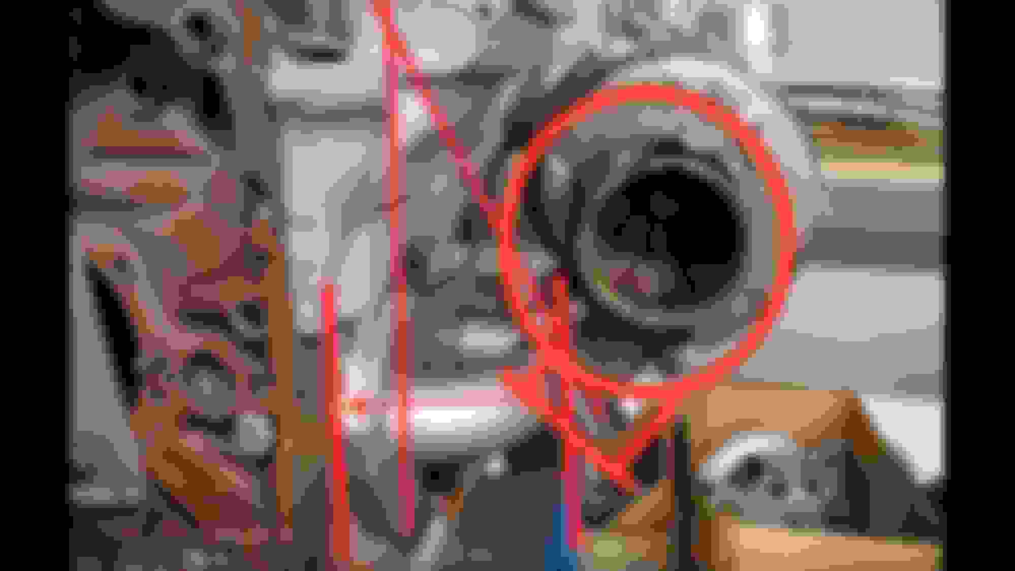
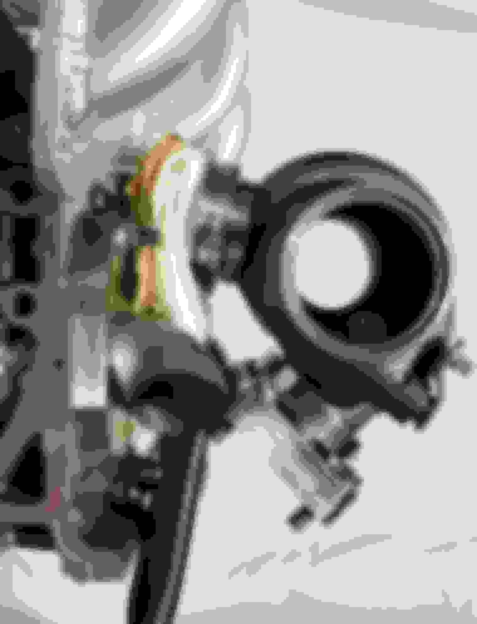
This is how I had to position it (ignore all the junk I spaced it with the housing on my living room floor) for the compressor to clear the manifold piping on the other side. This 0.92AR Pulsar V-band IWG turbine housing is smaller than the Garrett 1.06 div T4. The Garrett turbine will be closer to the intake in that regard, but still good clearance. Elbows out of the flange are angled 45�.
The piping then needs to loop around rams horn style, though per the flange method we discussed, it can come into the flange straight in from the side, rather looping down under and in to minimize the length. The wastegate canister fits right into the space above the subframe where the Renesis engine mount was previously.
Team, that last image you shared clears up alot thanks. The 180deg concept is pretty sneaky tubing wise.
We mainly worked on my friend's 73' 240z this weekend. However I was able to get some stuff done on the Rew. I was hoping to get the JDL surge tank in, but have to order longer hose for the siphon line.
Modified the CX mount to fit the nicon pan. This allowed us to get the engine finally in place and centered. Engine and trans had to slide back to match the stock location on the PPF. Picked up some JIS fasteners to start replacing old crusty ones. Only spent 100$ on quite alot. Found my rear iron belhousing cover on a shelf from the REN and it seems to bolt right in. Also persuaded the firewall a little bit to fit the new LIM positioning......youd think if CX made a mount brace and a LIM swap kit that you wouldnt be rubbing on the firewall.
Was brainstorming some more on it this morning and think there’s a similar but better way to do it for those using piping elbows i.e. Warrior777’s situation. Will try to post some more pics soon to demonstrate the idea.
.
Appreciate that TeamRX8.
I'm trying to get the turbo in the perfect position with the mock up exhaust manifold but it's difficult to achieve the angle and get the correct measurements.


 07-25-2023, 08:55 PM


 . I ordered a 2x7ft roll and still have like 2x2ft+ left for charge pipes or the lower intake tubes.