When you click on links to various merchants on this site and make a purchase, this can result in this site earning a commission. Affiliate programs and affiliations include, but are not limited to, the eBay Partner Network.
Assuming I get to running my fuel lines before you get your car finished I will get some of those printed and sent your way. I'll run into the same issue.
Fuel pump unit has been redone. Basically just removed the surge tank and lifter pump. Tapped the return through and barbed the siphon on the return. Then added the holley fuel mats.
Then I redid the oil lines in 10an coated PTFE. Which I found that I already had most of the fittings from a previous project.
Also hooked up the alternator with some info from Fickert and RotaryMachineRX. I went with one of the 180amp DCpower alternators. For wiring it was about 2ft long. The blue lead went to 12v battery and the yellow went to 470Ohm Fused on ignition switch. I just used an add a fuse to the Wipers slot. Note that the alternator will still need a bracket to hold the top mount. This will likely just go to the two threaded holes on top of the front cover.
Another picture dump update from the closing of 2023.
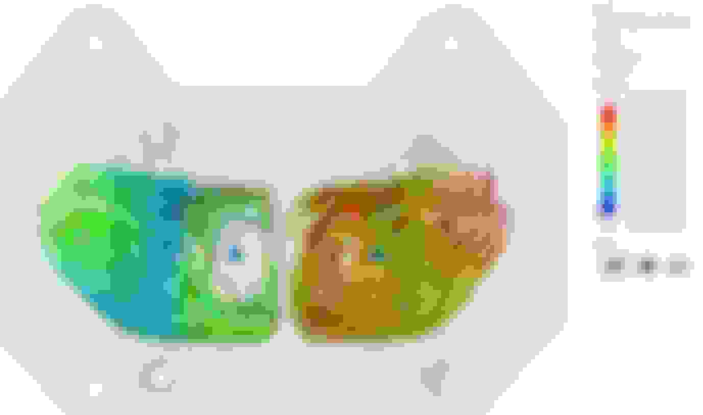
The printfarm at work had some open time this week, so we are moving forward with printing the manifold. Before printing, one of my other buddies was able to run some cfd on the design. We did some iteration to reduce turbulence and flow separation. Luckily we had caught that a part of the design had not mirrored properly. Most of our changes were focused on keeping the flow attached around the first bend.
Previous Previous Final Final
Oil pedestal design, close to final. 10anOrb and two 1/8npt ports. Next iteration will angle the 10anOrb out more towards the front of the engine.
I am trying to keep the oil pedestal a machinable part.
For the sim I found a way to calculate exhaust velocity from the capacity and rpm of the engine. For NA 1.3L at 4500rpm I got 60mph per exhaust port. For lets say 14.7psi boost 1.3L I just treated it as double displacement so 2.6L at 4500 rpm I got 120mph per exhaust port. at 9k rpm those values essentially double.
So for sim parameters we did
velocity = 60mph or 120mph or 240mph
pressure = atm or 14.7psi boost
Gas temp = 1500f to 1800f
Engine flange temp = 500f (just guessed, shouldn't affect much)
Turbo flange temp = 500f (just guessed, shouldn't affect much)
Now if you notice in the sim I had him add a 3inch extension with a slight draft to mimic the initial turbine flow.
I've done some extensive monitoring with an IR thermometer on these flanges, this is a good estimate of a hot setup..... typically after cruise/spirited driving in most FD's and my own car I'm seeing the exterior of these flanges anywhere from 350F to 430F. Of course those are taken immediately after the car is shut down so are likely a bit cooler than if the car is in the middle of sustained WOT driving. This is the downpipe to turbine connection and the turbine to manifold flange I'm measuring. I've tried measuring the flange temp on the block but stopped when it was MUCH cooler than the other two.
Last edited by RotaryMachineRx; 01-05-2024 at 12:22 PM.
Well been busy rebuilding an wrx sti for our buddy in the service. He should be ecstatic once he gets back from sandland. I can't believe he didn't blow the engine. Blown headgasket, sparkplugs were like 3x the gap, coils were bloated, timing belt was missing chunks, intake was collapsed just before the turbo, injector wires were hanging on by a thread from strain.
The manifold has been printed at work and is waiting to go into the furnace. I also reached out for casting quotes and the local companies were quoting $6500 for a single or around $3500ea for a10qty..... Seems rather high to be honest. My brother wants to try his hand at casting some day, so this may be a fun summer project.
Also I finished installing the trunk mounted battery.
This was mostly depowdered, which is what you see in the runners.
Forgot to post last weekend, but I did many things that I did not take pictures of. Mainly random touchup stuff on wires and interior. Also I wired and tested the fuel pumps. So far I have the underbody hardlines done and I just made a loop in the engine bay to run the pumps. Both ran and a couple leaks were fixed.
I do have some pics of the:
intercooler install
Radiator planning (ordering now)
Rx8 Oil Cooler thermostat delete. (running a 185c thermostat in the improved racing remote filter unit)
Got a new job, made out like a bandit. working 5 mins from home should save me a lot in gas and premix. Also no more income tax working in NH.
Found a cheap greddy kit for my poverty rat daily rx8..... been dealing with boost creep issues probably due to 3in no cat exhaust.
Building up my spare renesis for the rat rx8.
Testing out some various paint combos to see what I like for engine bay parts.
Got another JDM 5 speed with the help of Fickert
REW update
Finished the 3d Inconel 625 metal print before leaving the old job, see pics below. Had to do quite a bit of mass reduction to prevent sintering issues, reduced from 3.5kg to 2.5kg Inconel. I was hesitant to reduce the t4 flange by much more, even though I probably could have. One runner had a crack that developed during sintering and was welded up. Still need to post machine, tap, and sandblast the part. You can also see a slight layer shift that happened. More pics once i clean it up.
Found out about craftcloud and quoted out a stainless version of the manifold at around $600us per. Plus I would need to post machine and tap.
Started cleaning up the engine harness, contemplating extending to run into the passenger cabin......its rather gooey.
Received my custom radiator from CGJ, should be mounting next.
Made a basic coolant diagram on the google sheet Link Once the radiator is in I can start buying fittings.
Fighting off the horde of mice that are somehow getting into the trunk. I think they are coming up the rear fenders. Stuffed a bunch of dryer sheets in there.


 12-16-2023, 10:15 PM