When you click on links to various merchants on this site and make a purchase, this can result in this site earning a commission. Affiliate programs and affiliations include, but are not limited to, the eBay Partner Network.
Yep, mine is the same deal, a low pressure lift pump in the passenger's side, with a hydramat on the bottom, pumped over using the factory siphon tube.
I defeated the factory fuel pressure regulator and regulated fuel pressure with an Aeromotive 1:1. Obviously once the in-tank FPR is defeated you don't have any more siphon.
How hard would it be to increase the internally-regulated pressure instead of just defeating it?
How hard would it be to increase the internally-regulated pressure instead of just defeating it?
Could probably be done, but it would be very trial-and-error and that assembly is crimped / swaged together. I wouldn't want to attempt it and risk something failing down the line. Much better to use a quality FPR which compensates for manifold pressure.
Could probably be done, but it would be very trial-and-error and that assembly is crimped / swaged together. I wouldn't want to attempt it and risk something failing down the line. Much better to use a quality FPR which compensates for manifold pressure.
I'm planning to PWM the fuel pump but I don't want to lose the factory siphon setup. I was hoping to do a 60psi base pressure + ~20psi to reference boost, but may just go 40psi base.
From what I can gather, there is no way to avoid running a new fuel supply line to the rail under the car but I can use the stock hard line as a return.
Last edited by Warrior777; 04-05-2022 at 12:00 PM.
John V, did you ditch your first setup due to fuel starvation on hard turns during track time? Where you not happy with the venturi setup due to this?
Also I'm thinking, I should just add a pulse dampener now instead of later...
Last edited by Warrior777; 04-05-2022 at 12:02 PM.
From what I can gather, there is no way to avoid running a new fuel supply line to the rail under the car but I can use the stock hard line as a return.
Pretty much.
Originally Posted by Warrior777
John V, did you ditch your first setup due to fuel starvation on hard turns during track time? Where you not happy with the venturi setup due to this?
Also I'm thinking, I should just add a pulse dampener now instead of later...
I thought I was getting fuel starvation, but it ended up being a trigger problem.
I like this current setup better, though, as it's much easier to package and work on.
You have to remember that E85 requires a 35% flow increase over gasoline for the same HP in addition to the 30% additional volume required by a rotary engine over a reciprocating engine.
However, when it’s all said and done the OE fuel line can likely support more than some people might suppose or fully understand as per the link below. Which a return system is essentially pumping more than required up to the engine with the excess then having to return all the way back to the tank in the rear. There are sound reasons why manufacturers aren’t doing it that way any more. Not that the OE system doesn’t do that, just that it does it inside the tank rather than make that big loop around. Even if you don’t do it in the tank, it can still be done back near the tank in a short loop instead.
Is the stock fuel line diameter just not enough to support big power?
When I was building my car I concluded that it was probably sufficient for a piston engine making ~ 500 chp on E85 but I didn't want to risk it. I was told by a lot of "experts" that the dead-head fuel setup I'm running now would simply not work at these power levels but the data from my car suggests it's all working perfectly.
Thanks for that video Team. Brings up so many questions I have and reminds me how little I understand about cars in reality. Let the researching continue. Now, I'm wondering if I should use the hardline as a return or not and places doubt on using a fuel pressure damper. Seeing as how my rails are not tapped for a damper and its best to use them on the rail, I think I may skip this for now.
I see that the rx7 map sensor is connected to the rx7 UIM and the rx8 map sensor is not connected to the UIM. I assume I will be using rx8 map senor with the rx7 engine and controlling this by Adaptronic ECU/Tuning and I would connect the rx8 map sensor to the rx7 UIM with a proper gas filter. Is this correct?
Also, from what I understand since I'm using the rx8 throttle body, I will not need the rx7 idle control valve, is this correct?
Where do I go about finding everything that is going to need vacuum lines or everything that needs to be connected to the UIM I'm using?
If you're using a DBW throttle body you don't need an idle control valve.
If you have the Adaptronic then I’d recommend an external MAP sensor. The internal ones are known to fail. If it’s the Modular ecu the DBW is all setup. If it’s the Select version it will require an air valve to be setup and wired separately into the Select output pins.
Thanks for that video Team. Brings up so many questions I have and reminds me how little I understand about cars in reality. Let the researching continue. Now, I'm wondering if I should use the hardline as a return or not and places doubt on using a fuel pressure damper. Seeing as how my rails are not tapped for a damper and its best to use them on the rail, I think I may skip this for now.
I see that the rx7 map sensor is connected to the rx7 UIM and the rx8 map sensor is not connected to the UIM. I assume I will be using rx8 map senor with the rx7 engine and controlling this by Adaptronic ECU/Tuning and I would connect the rx8 map sensor to the rx7 UIM with a proper gas filter. Is this correct?
Also, from what I understand since I'm using the rx8 throttle body, I will not need the rx7 idle control valve, is this correct?
Where do I go about finding everything that is going to need vacuum lines or everything that needs to be connected to the UIM I'm using?
As you've already noted above the Adaptronic actually has 2 MAP sensors built right in; the IMAP and EMAP. As Team notes they have a bit of a reputation for failing so lots of guys will pin in an external sensor. I'm currently using the internal IMAP and if I do find it starts to fail will utilize the EMAP as a back-up since that is currently unused. That or just go with an external MAP but so far I haven't run into any issues.
Vacuum lines for this swap will be super simple, you only need lines for the gauges you are using and your manifold reference FPR. My current vacuum lines are limited to:
- Adaptronic internal MAP
- Mechanical Boost Gauge in my dash
- BOV Signal Line
- FPR signal line
- Brake Booster
- I also have EBC vacuum lines but these go from the nipple on my EFR compressor housing, to the EBC solenoid, to the Wastegate actuator rather than to the UIM/LIM.
You won't need any of the RX7 TB or idle stuff if you're using the Rx8 DBW which is set-up already on the Adaptronic PNP.
The only other thing you need to consider is a IAT sensor. Most guys utilize an RX7 (or just an aftermarket sensor) and take the two temperature wires from the RX8 MAF connector and wire those to the new IAT sensor. That's what I did. If you utilize an FFE trigger wheel with the reluctor sensor you shouldn't need to do any wiring for trigger wheel, should be just PNP.
Last edited by RotaryMachineRx; 04-11-2022 at 02:24 PM.
Thanks for the info. This is great.
Jesse about the IAT I was planning to buy the bracket for the rx8 MAF and plumb this into the intake and use the built in IAT. I will retain air straightener screens. I should be able to also use the built in MAP sensors and the rx8 MAF. After researching it appears to be good science to use both of these measurements to calculate proper Air fuel ratio. Does that make sense?
Team, I suppose at this point I will use the built in MAP sensors with the modular then fix it if needed??? I will keep in mind that I might need to add an external MAP sensor and maybe just have it plugged into the rx7 intake in advance.
Last edited by Warrior777; 04-12-2022 at 02:02 PM.
Thanks for the info. This is great.
Jesse about the IAT I was planning to buy the bracket for the rx8 MAF and plumb this into the intake and use the built in IAT. I will retain air straightener screens. I should be able to also use the built in MAP sensors and the rx8 MAF. After researching it appears to be good science to use both of these measurements to calculate proper Air fuel ratio. Does that make sense?
Team, I suppose at this point I will use the built in MAP sensors with the modular then fix it if needed??? I will keep in mind that I might need to add an external MAP sensor and maybe just have it plugged into the rx7 intake in advance.
All your tuning will be based on MAP; I'm not sure you can utilize MAF and MAP at same time. AFR's are directly measured by your Adaptronic wideband module/O2 sensor. I don't believe the MAF IAT is "fast-acting".... so you are likely better off wiring in a Fast-Acting Air Temp sensor as I believe IAT is used for fuel density calcs by Adaptronic...
Because I was just looking into this for someone else, on your MAF connector there is 5 wires in a line. Pins D & E are you IAT here:
Last edited by RotaryMachineRx; 04-13-2022 at 12:49 PM.
I want to say Pin C is the MAF signal, but am trusting my memory. I’d definitely de-pin it if the MAF is hooked up. The one thing that drove me crazy for several months on the Select ecu with the REW converted car I bought is that it was conflicting with and throwing off the MAP signal, regardless of it being the internal MAP or a wired in external MAP.
Adaptronic doesn’t state this anywhere that I know of, but the signal for each go to the same place in the ecu, or at least it does on the Select ecu. I’m sure you can appreciate that 3V on the MAF is going to be quite a different airflow equivalent than 3V on a multi-BAR Map sensor. In several cases the external MAP sensor failed electronically even. I concluded it was the voltage from the MAF feeding back to that was causing it. I didn’t really investigate it at the point of figuring out what the issue was, but the MAF sensor signal didn’t seem to be proper either and it was possibly damaged as well for the same reason. Just that everything was happy and functioning properly once I pulled the MAF signal pin.
Which is kind of important when exceeding 30 psig boost
.
Agreed, I think trying to run both would cause issues. I'll refrain to my previous comments because I know it works! haha; my recommendation is to get a fast acting IAT sensor and pin the wires from the MAF D & E to it. This means the harness connector to the ECU shouldn't need to be modified at all either.
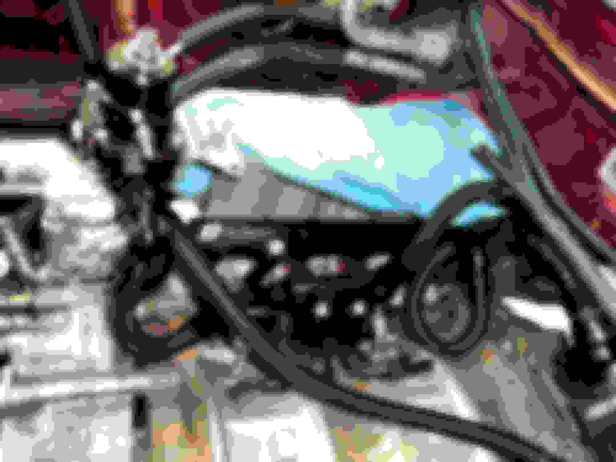
A little update with pictures. This is my idea for the fuel lines. Added a feed line and using the oem fuel line as a return. What do you guys think? Anything raise a red flag?
I showed my wife my work and she said “you are going to burn it down”…
Also, I think I’ve decided to go ahead and plumb the flex fuel sensor. I’m thinking of adding it just after the feed line turns upward into the engine bay along the fire wall adjacent to the transmission tunnel. Is that an okay idea?
Next, I will wire up the two pumps and run my ground.
Looks like you decided to run the fuel rails in parallel, curious, what was your deciding factor for going that route as I know we had some indecisive conversations about it in the past? Looks super clean, really like that black nylon braided hose, in hindsight I wish i went that route over the stainless braided. I don't see any issues popping up, routing/plumbing all looks proper to me.
It was a tough decision but in my mind separating the the fuel rails and allowing them to have their own fuel supply would potentially be an improvement (against pressure drop) and in higher power situations the parallel was an advantage, which I would like to leave as an option. I read in one of the forums that one of the fuel companies said that parallel systems help the regulator achieve more consistent fuel pressure to each rail?? Who knows about that one.
Also, I had bought a bunch of stuff off a few members who quit on their rew swap so I already had almost all the extra A/N connectors I needed which eliminated a substantial cost difference.
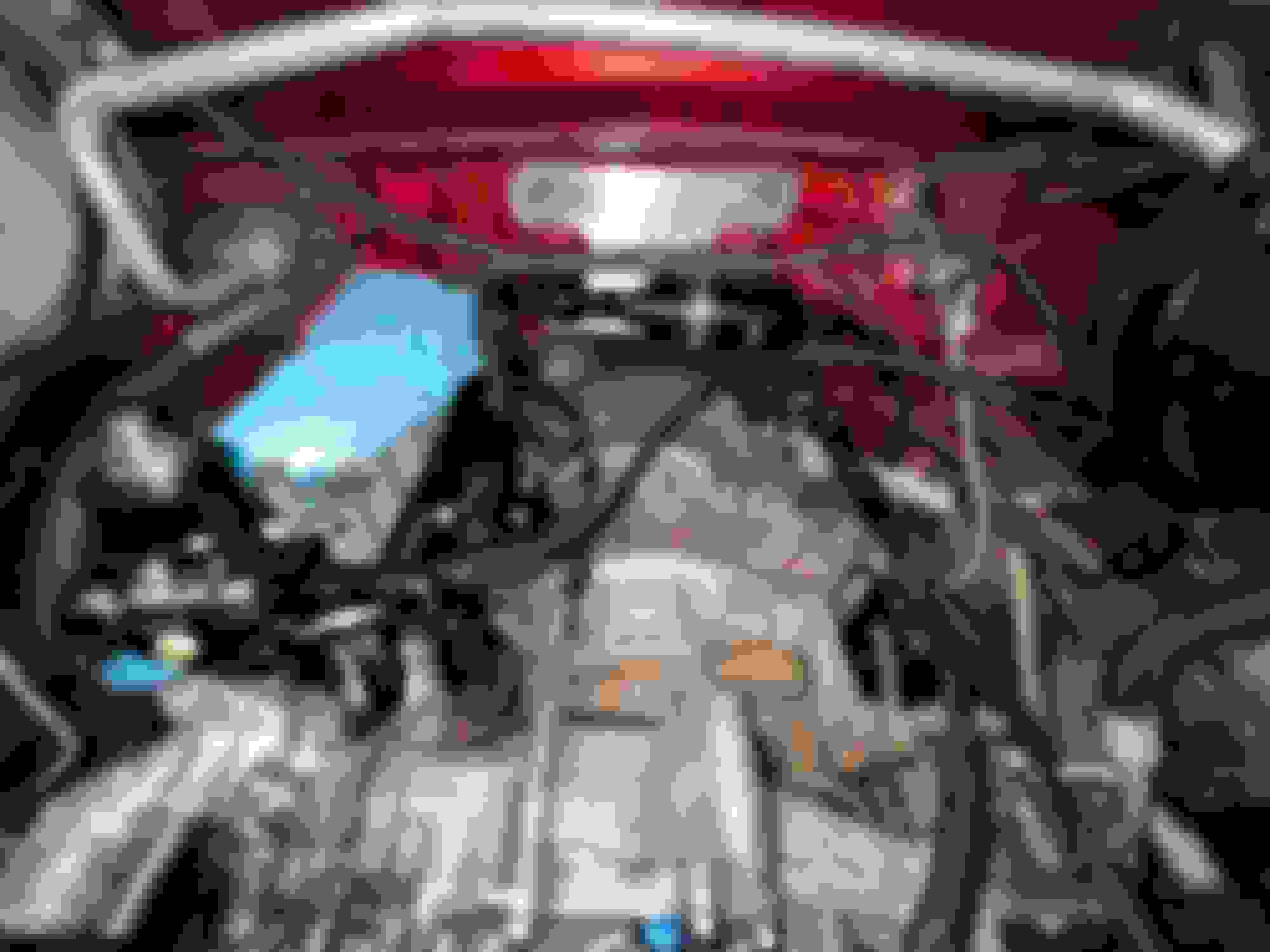
Here is a picture with the UIM in place, I had meant for this to be included with the others above.
 04-03-2022, 06:06 AM