DIY: AEM Twin-Fire CDI Ignition Install
 05-01-2006, 02:40 PM
#1

DIY: AEM Twin-Fire CDI Ignition Install
AEM Twin-Fire CDI Ignition Install
As many of us have discovered, the factory coils are prone to burning and failure due to heat, stress and over-voltage when used in conjunction with the Greddy E-Manage or other EMS systems.
The AEM Twin-Fire CDI (Capacitive Discharge Ignition) offers several advantages for the RX-8 over both the OEM coils and other CDI ignitions from other manufacturers.
1) It has two separate capacitors so it is able to fire the leading AND trailing plugs at the same time
2) It is very compact
3) The MSD DIS coils that I used could probably continue to work indefinately even if you set them on fire in a pot of molten lava
4) CDIs fire the plugs with considerably more voltage and longer duration (at lower RPMs) than the OEM igntion which results in a more complete burn of the combustion charge and less potential for plug fouling and a smoother idle

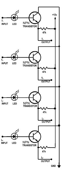
This installation requires a few non-typical skills including an understanding of hobbyist-level electronic circuit building. The output signal from the PCM and/or E-Manage is a positive pulse and the AEM expects to see a signal pulled to ground. This means you have to build a driver circuit. I've included this diagram which shows the schematic for the driver which includes a set of LEDs to indicate the presence of ignition signals:
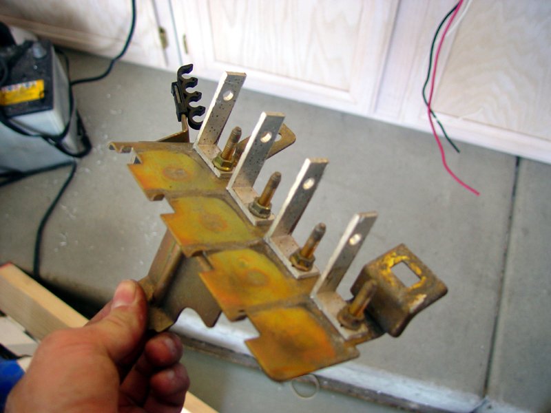
The OEM coils are removed and a set of brackets are created to support the 4 new coils:
The 4 new coils are mounted to the OEM bracket and grounded with separate wires to ensure a good ground connection. The trigger and source wires (black and orange, respectively) are wired with individual connectors to mate with the AEM harness. The two leading coils have their source wires connected through a common connector to one output of the CDI and the two trailing are wired similarly to their own source.

The new assembly is mounted in the OEM position:
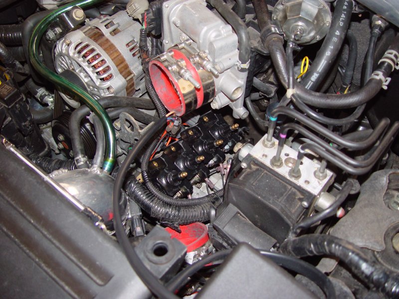
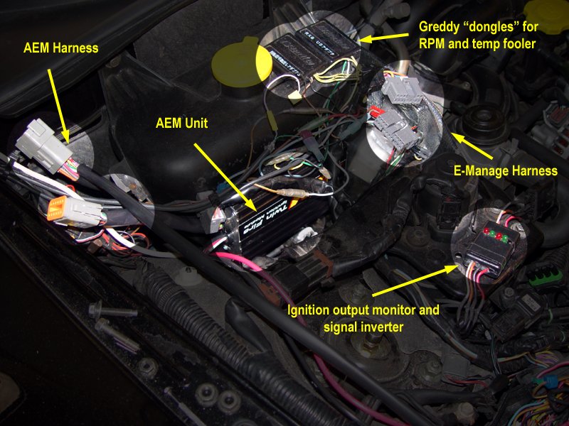
I mounted the AEM module just below my E-Manage in the engine bay. This is probably not an optimum location because of the heat it is exposed to, but I am lazy and I am planning on re-wiring almost all of the aftermarket electronics in the car to eliminate the rat's nest that has resulted from mulit-layer installations and experimentation over the last two years with different electronics in the car.
The three DIP switches on the AEM need to be configured to all be off. This sets the multi-strike to active, the firing to trailing edge and the frequency to every crank rev.
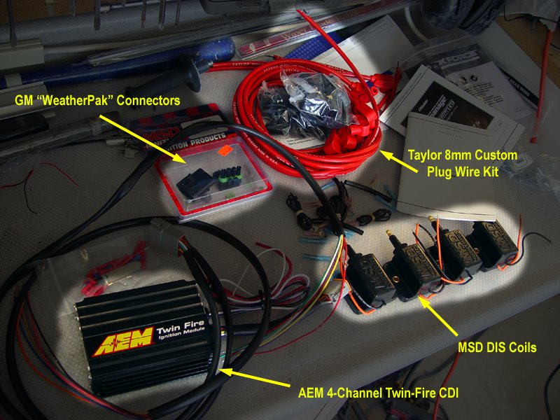
I fabricated a new set of plug wires. This is necessary because the OEM wires do not have the correct connector for the DIS coils. I used a Taylor 8mm "universal" kit.
As many of us have discovered, the factory coils are prone to burning and failure due to heat, stress and over-voltage when used in conjunction with the Greddy E-Manage or other EMS systems.
The AEM Twin-Fire CDI (Capacitive Discharge Ignition) offers several advantages for the RX-8 over both the OEM coils and other CDI ignitions from other manufacturers.
1) It has two separate capacitors so it is able to fire the leading AND trailing plugs at the same time
2) It is very compact
3) The MSD DIS coils that I used could probably continue to work indefinately even if you set them on fire in a pot of molten lava
4) CDIs fire the plugs with considerably more voltage and longer duration (at lower RPMs) than the OEM igntion which results in a more complete burn of the combustion charge and less potential for plug fouling and a smoother idle
This installation requires a few non-typical skills including an understanding of hobbyist-level electronic circuit building. The output signal from the PCM and/or E-Manage is a positive pulse and the AEM expects to see a signal pulled to ground. This means you have to build a driver circuit. I've included this diagram which shows the schematic for the driver which includes a set of LEDs to indicate the presence of ignition signals:
The OEM coils are removed and a set of brackets are created to support the 4 new coils:
The 4 new coils are mounted to the OEM bracket and grounded with separate wires to ensure a good ground connection. The trigger and source wires (black and orange, respectively) are wired with individual connectors to mate with the AEM harness. The two leading coils have their source wires connected through a common connector to one output of the CDI and the two trailing are wired similarly to their own source.
The new assembly is mounted in the OEM position:
I mounted the AEM module just below my E-Manage in the engine bay. This is probably not an optimum location because of the heat it is exposed to, but I am lazy and I am planning on re-wiring almost all of the aftermarket electronics in the car to eliminate the rat's nest that has resulted from mulit-layer installations and experimentation over the last two years with different electronics in the car.
The three DIP switches on the AEM need to be configured to all be off. This sets the multi-strike to active, the firing to trailing edge and the frequency to every crank rev.
I fabricated a new set of plug wires. This is necessary because the OEM wires do not have the correct connector for the DIS coils. I used a Taylor 8mm "universal" kit.
Last edited by MazdaManiac; 09-28-2010 at 04:06 PM. Reason: �� 2008 MazdaManiac
 05-01-2006, 04:25 PM
#2
Working backwards:
I don't know if the OEM coils are going to be totally inadequate at any particular power level. It is possible that they are capable of putting out enough energy to keep the flame lit at elevated boost levels. However, the advantages of the CDI setup are manifold and power is but one.
Here are the items I used. Note that this assumed that an igntion harness was already in place. For those that are coming to this with an unmodified ignition/PCM system, you will need to splice the factory coil outputs at either the coil end or the PCM end.
(1) AEM 4 Channel Twin Fire Ignition PN# 30-2821
(4) MSD Blaster DIS Racing Ignition Coils PN# MSD-8230
(1) Taylor Universal Plug Wire Kit PN# TAY-73251
(2) MSD Weathertight Sealed Connectors PN# MSD-8171
(4) PNP Switching transistors (general, 20v min)
(4) 47k ohm, 1/4 watt resistors
(4) LEDs, 3v min (I used yellow for leading and green for trailing)
(1) small project board (Radio Shack)
assorted wire, connectors, solder, etc.
The brackets are cut from aluminum channel stock that is available at Home Depot or Lowe's.
The coils can be mounted in any orientation - they coontain no oil like old-fashion coils and are completely potted and sealed.
I don't know if the heat damage is necessarily arcing - it may simply be extreme heat from a combination of environment and load. But that would have to be a LOT of heat to burn the zinc-coated metal of the bracket.
Last edited by MazdaManiac; 04-18-2008 at 05:26 PM. Reason: �� 2008 MazdaManiac
05-01-2006, 05:46 PM
#4

nice job, I saw Yaw's writeup on the circuit switch
no progress on mine, just haven't had time t source the connector to fit the OE coil harness yet. It's just not my top priority at the moment. Think I may know where to source the connector though.
no progress on mine, just haven't had time t source the connector to fit the OE coil harness yet. It's just not my top priority at the moment. Think I may know where to source the connector though.
05-01-2006, 06:32 PM
#5
Originally Posted by lurch519
so how does it run with the twin fire.
I haven't driven it in boost yet. I posted the DIY 10 minutes after I finished the install. I'll flog it tonight. Its 100� out right now and I don't feel like driving in traffic.
Originally Posted by TeamRX8
nice job, I saw Yaw's writeup on the circuit switch
05-01-2006, 10:36 PM
#7
Originally Posted by TeamRX8
Same basic principle, though.
I don't have a dual-trace ocilloscope (I just have a single trace scope-meter), but it looks like the AEM with this switching circuit ends up advancing the spark a few degrees, which is bad. I think part of this is because of how quick it loads up and fires - the OEM system is slow and fires in the middle of the pulse. I'll probably have to build a buffer with a 555 timer or something similar to put the trigger a 1/2 wave later to get the timing square to avoid detonation.
05-02-2006, 01:03 AM
#8
Banned

Join Date: Oct 2005
Location: Ely, UK
Posts: 189
Likes: 0
Received 0 Likes
on
0 Posts
I wonder how well it will perform at higher rpms? It might give better combustion at lower rpms, but at 9K you have a lot more energy to be keeping up with. Will it be able to keep the longer duration (I doubt multiple sparks heh) spark?
05-02-2006, 09:15 AM
#10
Originally Posted by brillo
you think you'll notice any economy improvements?
Originally Posted by brillo
Assuming someone made more powerful coils for our car, would that have the same effect as your setup?
Originally Posted by Beodude123
I wonder how well it will perform at higher rpms? It might give better combustion at lower rpms, but at 9K you have a lot more energy to be keeping up with. Will it be able to keep the longer duration (I doubt multiple sparks heh) spark?
At 9k, it won't be in multi-strike anymore because of time constraints, but it won't loose any energy either.
05-02-2006, 06:41 PM
#12
Originally Posted by Charles R. Hill
After looking in the 2006 MSD catalog I am a bit curious as to the durability of the 8230 coil since it is a race-only coil. I wonder if the 8232, which is similar, might prove to be a bit more durable over the long-term. Plus, MSD provides the electrical measurements for the 8232 but not the 8230. Any thoughts?
CRH
CRH
Conversely, I can only find a passing reference to the 8232 on MSD's site with regards to a Chrysler DIS ignition. It just looks like the 3230 repackaged with a connector rather than leads.
 05-03-2006, 01:15 AM
#14
Well, no doubt it will see moisture in that position, though it wouldn't be inundated. I'd think the heat would boil it out way before it could oxidize the plating.
That wouldn't explain the burns on the epoxy potting on the bottom of the coils, however.
That wouldn't explain the burns on the epoxy potting on the bottom of the coils, however.
05-04-2006, 01:54 AM
#15
I recently encountered a drivability problem, appears that all four OE coils are defective, only 3300 miles on them ...
https://www.rx8club.com/series-i-tech-garage-22/breaking-up-under-part-throttle-88951/
https://www.rx8club.com/series-i-tech-garage-22/breaking-up-under-part-throttle-88951/
 07-31-2006, 09:44 PM
#17
Go Texas Longhorns!

I was thinking today about upgraded coils and had a thought, has anyone looked into other Mazda vehicles that might have stronger coils we could use such as the Mazdaspeed6? I wonder if the connectors are the same? Just a random thought, might be worth investigating.
08-01-2006, 08:52 PM
#18
Originally Posted by colin204
any updates?
not here, I've been buried at work, no spare time at all
it turned out I didn't have a coil problem afterall, car is running strong so it hasn't been a priority under the circumstances, keeping 6 spd trans from blowing up is higher on the list
 08-01-2006, 08:56 PM
#19
Originally Posted by TeamRX8
not here, I've been buried at work, no spare time at all
it turned out I didn't have a coil problem afterall, car is running strong so it hasn't been a priority under the circumstances, keeping 6 spd trans from blowing up is higher on the list
it turned out I didn't have a coil problem afterall, car is running strong so it hasn't been a priority under the circumstances, keeping 6 spd trans from blowing up is higher on the list
beers
 08-23-2006, 11:21 PM
#20
Air + Fuel + Spark = Boom

Join Date: Nov 2005
Location: Brunei. Do u know where tht is?
Posts: 384
Likes: 0
Received 0 Likes
on
0 Posts
If i just purchase a set of coils + a set of the weatherpack connectors.. they will work like stock right? I will not need to build a circuit of any sort?
I already have a HKS twin power for the rx-8.. I do not want to cut the connectors
I already have a HKS twin power for the rx-8.. I do not want to cut the connectors
 08-24-2006, 08:21 PM
#23
look at the electrical sematic in the manuel and you will see an indiviual black grounding wire from each coil. people have been spicing into that and running a ground wire from each coil to the negative post on the battery. Read the "grounding kit" thread
olddragger
olddragger
08-24-2006, 10:47 PM
#24
Originally Posted by olddragger
look at the electrical sematic in the manuel and you will see an indiviual black grounding wire from each coil. people have been spicing into that and running a ground wire from each coil to the negative post on the battery. Read the "grounding kit" thread
olddragger
olddragger