DIY: Battery relocation to trunk
 02-28-2013, 07:21 PM
#251
Registered

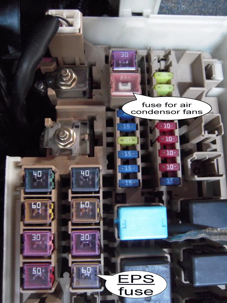
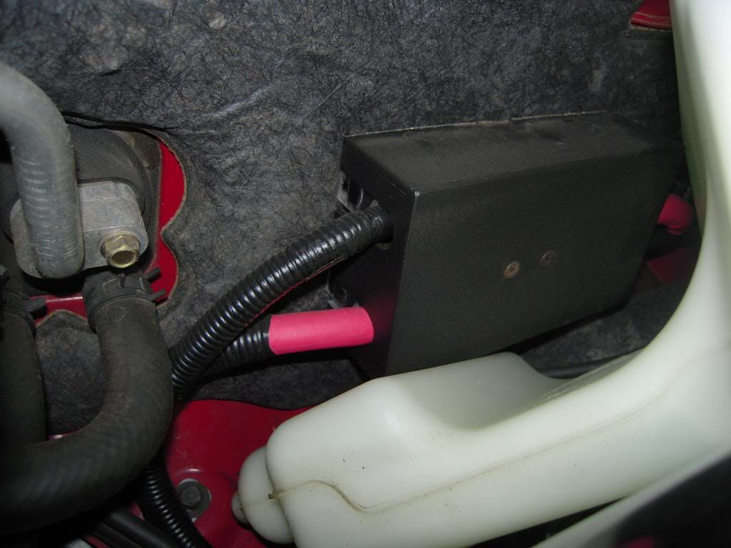
paimon - Here is a photo of where my EPS fuse is
Heres a couple more photos of my distribution block, its made of brass plate, and the bolts, nuts and screws are all brass and this is screwed to solid acrylic plastic which has a seperate acrylic plastic base, so nothing can contact any part of the vehicle.
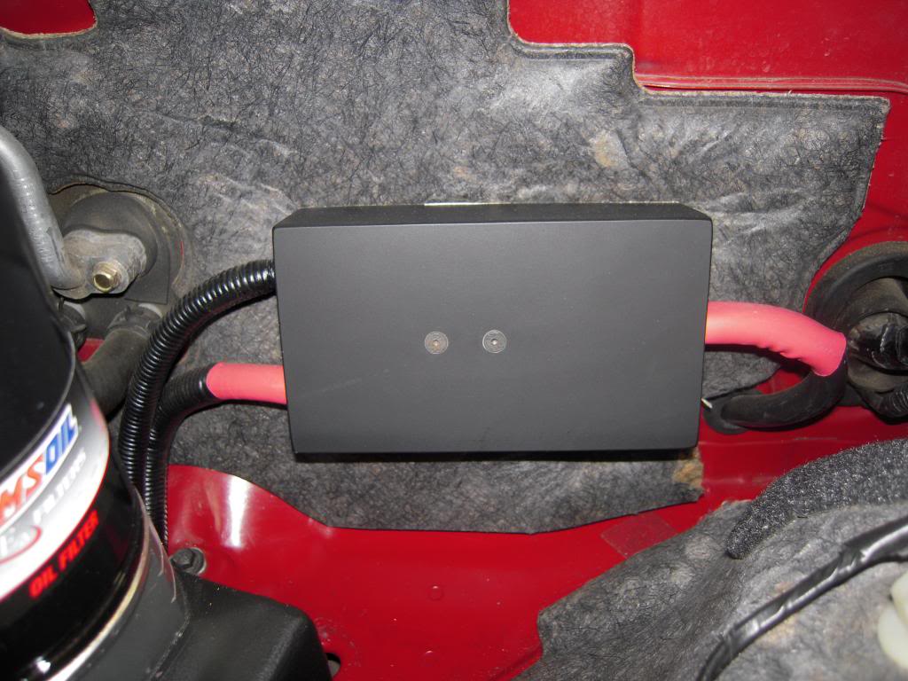
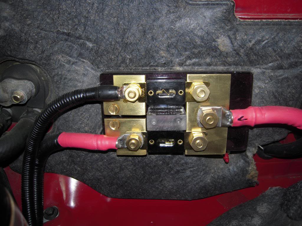
The 100amp fuse is for the 4 gauge that goes to the factory fuse box.
The 250amp fuse is for the 2 gauge that goes to the starter motor.
Rotaman
Heres a couple more photos of my distribution block, its made of brass plate, and the bolts, nuts and screws are all brass and this is screwed to solid acrylic plastic which has a seperate acrylic plastic base, so nothing can contact any part of the vehicle.
The 100amp fuse is for the 4 gauge that goes to the factory fuse box.
The 250amp fuse is for the 2 gauge that goes to the starter motor.
Rotaman
 03-01-2013, 11:28 AM
#252
Registered

Join Date: Apr 2009
Posts: 918
Likes: 0
Received 0 Likes
on
0 Posts
The piece of ply I have in the back there runs the full width of the car and is screwed down to the floor at multiple points, it will never rip off the floor.
I use that same piece of ply to hold down my subtube as well.
Yes I do have a large 4 channel amp in the car, but the distribution block is not used for that. The amp gets its power direct from the battery.
Must admit I don't know anything about the Okada Project plasma lift, but it looks like a type of CDI unit.
If you are looking into CDI units, try M&W in Australia, they make CDI's especially for Rotaries. Very good products.
Rotaman
is this it?
M&W Ignitions was formed in 1996 with the goal of being the number one performance ignition system supplier in Australia - Inductive Ignition Systems
i had to google what is a CDI... the only two prodcuts that i previously know that made these 'stabilizers' were the HKS twin power unit and this Okada...
03-01-2013, 12:25 PM
#253

Piamon At 25ft a copper 2awg wire with a current draw of 100amps should only lose 6.5%. I think the cable yard stuff is a bit nicer then standard 2 gauge cable. I would guess you would see should see more of a drop in voltage then your normal battery set up but not as much as you are seeing. I would bet if someone did the same readings as you with the battery being wired 100% oem you would still see about the same numbers as you are now. I am curious as to what the actual amp draw would be at start up.
03-01-2013, 03:47 PM
#254
Registered
Blacknightz - Thats them. The unit you would be looking for which is specifically for Rotaries would be the Pro-14/R. But that is only if you are looking for a CDI unit. M&W make produts for Motec, so they products are good quality. But since I don't know what the Okada Project plasma lift actually is, these may not be what you want. For all I know the Okada Project plasma lift may just be a large Capacitor.
I use to have one of the M&W CDI units on my old RX2. If you want to have a look at one. Look under my profile and check out the photos of my old RX2, you will see one of the engine bay and the little box next to the over flow bottle is the CDI unit.
Rotaman
I use to have one of the M&W CDI units on my old RX2. If you want to have a look at one. Look under my profile and check out the photos of my old RX2, you will see one of the engine bay and the little box next to the over flow bottle is the CDI unit.
Rotaman
03-03-2013, 01:04 PM
#255
Registered
Join Date: Apr 2009
Posts: 918
Likes: 0
Received 0 Likes
on
0 Posts
Blacknightz - Thats them. The unit you would be looking for which is specifically for Rotaries would be the Pro-14/R. But that is only if you are looking for a CDI unit. M&W make produts for Motec, so they products are good quality. But since I don't know what the Okada Project plasma lift actually is, these may not be what you want. For all I know the Okada Project plasma lift may just be a large Capacitor.
I use to have one of the M&W CDI units on my old RX2. If you want to have a look at one. Look under my profile and check out the photos of my old RX2, you will see one of the engine bay and the little box next to the over flow bottle is the CDI unit.
Rotaman
I use to have one of the M&W CDI units on my old RX2. If you want to have a look at one. Look under my profile and check out the photos of my old RX2, you will see one of the engine bay and the little box next to the over flow bottle is the CDI unit.
Rotaman
thanks Mate! didnt know they were doing stuff for MOTEC... now that is assurance...
03-04-2013, 07:16 AM
#256

Rota; So in your opinion, would you say I should just trim off my ground wire and just ground to a chassis bolt close to my battery, like the rear seat belt anchor or rear seat anchor bolt?
FWIW I have a short < 3ft ground that is going to the rear strut tower, and the long ground running to my engine bay for the added insurance of a solid short ground and a solid engine bay ground ... but if I can save some wire and complexity that would be nice too.
FWIW I have a short < 3ft ground that is going to the rear strut tower, and the long ground running to my engine bay for the added insurance of a solid short ground and a solid engine bay ground ... but if I can save some wire and complexity that would be nice too.

 03-04-2013, 10:11 AM
#260
Ground to the Chassis or Run a Ground Cable? CE Auto Electric Supply Partners with D'Amore Engineering to answer - Video on Pg 5! - Page 5 - CE Auto Electric Supply � Providing Solutions to all of your Automotive Electrical Needs - SMD Forum
just reinforcing what everyone already knows.
Based on what Rotaman is saying, looks like the 8 has pretty good continuity through the chassis so it would be feasible to assume similar results.
just reinforcing what everyone already knows.
Based on what Rotaman is saying, looks like the 8 has pretty good continuity through the chassis so it would be feasible to assume similar results.
03-04-2013, 03:55 PM
#261
Registered
Rota; So in your opinion, would you say I should just trim off my ground wire and just ground to a chassis bolt close to my battery, like the rear seat belt anchor or rear seat anchor bolt?
FWIW I have a short < 3ft ground that is going to the rear strut tower, and the long ground running to my engine bay for the added insurance of a solid short ground and a solid engine bay ground ... but if I can save some wire and complexity that would be nice too.
FWIW I have a short < 3ft ground that is going to the rear strut tower, and the long ground running to my engine bay for the added insurance of a solid short ground and a solid engine bay ground ... but if I can save some wire and complexity that would be nice too.
I don't suggest that you use any battery earth mounting point that has anything else mounted to it like a seat belt. The problem with those type of anchor points is that they are only spot welded in place and you don't know how good a contact they have with the chassis as in current flow.
The problem with having anything else on the same mounting point is movement between two objects, especially a seatbelt mount.
whoever is suggesting running an earth cable from the front to the rear of the car, that is just stupid. Go and look up some current flow charts for the cable size you are looking at and you will see that running any cable long lengths is not a great idea.
Keep any cable run as short as possible for maximum current flow.
Think about this, a long cable run in a car would be from front to rear, that would be about 3metres ( 9 + feet ), now a good quality cable of 000 or 00 awg might give you 200 - 300 amps over that distance. Where'as using the chassis would easily give you 500 - 1000amps? Not that you will ever need that much current flow.
How much current flow will you get from 2awg or 4awg cable, maybe 150amps or at a stretch maybe 200amps before it starts becoming a heater.
So you see the best thing is to run as short a cable as possible and only run one cable if you have too.
Because in the end the main restriction in a good battery system will be the positive battery cable run from the front to the rear.
Rotaman
Last edited by Rotaman; 03-04-2013 at 07:53 PM.
03-04-2013, 08:03 PM
#263
Registered
Good to hear that you have sorted your little problem.
Obviously you must have had a poor connection with the previous posistion.
Also I don't have a welder either, I just had an engineer weld in a treaded steel block onto the chassis under the rear seat area.
Interesting isnt' it how little things can end up causing big problems when you are'nt sure of what you are doing or don't realise how critical a good conection can be when it comes to 12v systems.
Have fun
Rotaman
03-05-2013, 05:39 AM
#264
Registered
Join Date: Apr 2009
Posts: 918
Likes: 0
Received 0 Likes
on
0 Posts
Paimon - My opinion is what I have already said and shown in my photos.
I don't suggest that you use any battery earth mounting point that has anything else mounted to it like a seat belt. The problem with those type of anchor points is that they are only spot welded in place and you don't know how good a contact they have with the chassis as in current flow.
The problem with having anything else on the same mounting point is movement between two objects, especially a seatbelt mount.
whoever is suggesting running an earth cable from the front to the rear of the car, that is just stupid. Go and look up some current flow charts for the cable size you are looking at and you will see that running any cable long lengths is not a great idea.
Keep any cable run as short as possible for maximum current flow.
Think about this, a long cable run in a car would be from front to rear, that would be about 3metres ( 9 + feet ), now a good quality cable of 000 or 00 awg might give you 200 - 300 amps over that distance. Where'as using the chassis would easily give you 500 - 1000amps? Not that you will ever need that much current flow.
How much current flow will you get from 2awg or 4awg cable, maybe 150amps or at a stretch maybe 200amps before it starts becoming a heater.
So you see the best thing is to run as short a cable as possible and only run one cable if you have too.
Because in the end the main restriction in a good battery system will be the positive battery cable run from the front to the rear.
Rotaman
03-05-2013, 10:27 AM
#267
Registered User

Join Date: Oct 2012
Posts: 38
Likes: 0
Received 0 Likes
on
0 Posts
Probably really dumb question though, and random, but when I took off my bumper for my CAI install, what is the soft plastic foam thing behind the bumper? Mine ripped in half and I dont have one now. Does it affect the car at all other than I'm guessing to absorb the force kinda if the car crashes?
03-05-2013, 12:42 PM
#268
Probably really dumb question though, and random, but when I took off my bumper for my CAI install, what is the soft plastic foam thing behind the bumper? Mine ripped in half and I dont have one now. Does it affect the car at all other than I'm guessing to absorb the force kinda if the car crashes?
This threads topic is battery relocation. I am sure many people would be more then happy to help you with your question in more relevant thread. You may even be able to find your answer in search. Good luck.
03-05-2013, 01:00 PM
#269
Registered
There is certainly an advantage to having the battery in the boot when it comes to battery life, and probably for weight distribution as well.
But the down side is the distance that you have to run a cable and its extra size and weight.
As you have read in this tread, all the problems that are associated with not doing the job properly.
Don't take this modification lightly, this is one of those mods that needs to be done well, or you will have problems, especially with starting in cold weather.
Rotaman
03-05-2013, 01:30 PM
#270
Momentum Keeps Me Going

 Which leads to an alternative, solving many problems discussed herein, but generating its own. That is, to suitably insulate and/or ventilate a light battery in place underhood. This obviously eliminates problems related to the added weight of extra components, grounding difficulties, circuit complexity, and cable routing that a trunk relocation brings about.
This begs the question - which is better? That is, saving 30+ lbs underhood using insulation/ventilation techniques, or moving and possibly adding to overall car weight while distributing said weight elsewhere in the car doing a relocation? But that discussion likely belongs elsewhere.
 03-08-2013, 01:04 AM
#274
Registered
Join Date: Apr 2009
Posts: 918
Likes: 0
Received 0 Likes
on
0 Posts
Noob deduction....
-> those wanting to have longer battery life span and weight distribution, and at a loss of possibly a tad slower quick starting
= locate battery in the boot, opposite of driver side, use 0awg if possible for less, minimal resistance...
-> those wanting to have quick starting, still hot engine temps affecting the battery therefore battery life (not in stock location but to the side near firewall), no much affect on weight distribution
= still locate in trunk, less cabling needed, starting time unaffected,
03-11-2013, 06:57 AM
#275
Registered User

Join Date: Oct 2008
Posts: 5
Likes: 0
Received 0 Likes
on
0 Posts
Here are a few photos of my battery setup as it is today. My car is a JDM model, so remember this is right hand drive.
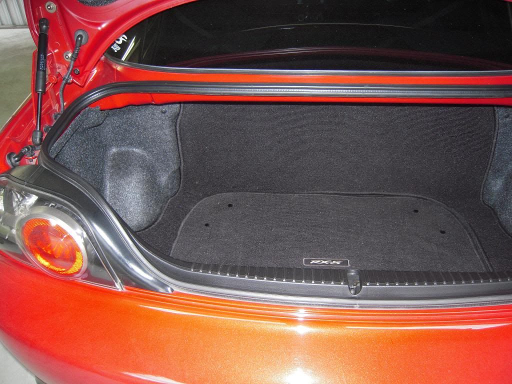
First photo of the boot with every thing in place
Second photo with carpet removed for access to battery etc.
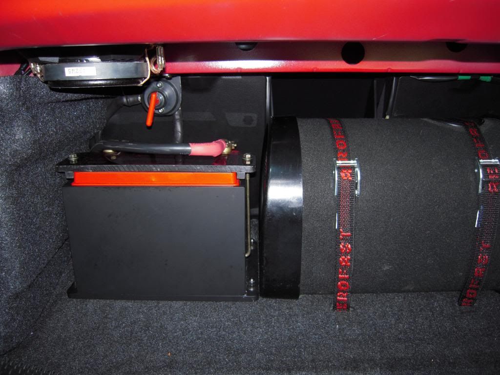
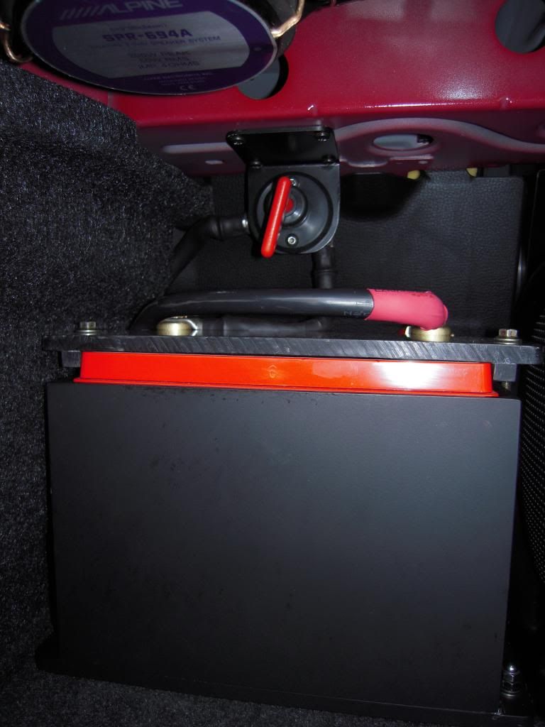
Third photo is close up of custom made battery box and quick cut off.
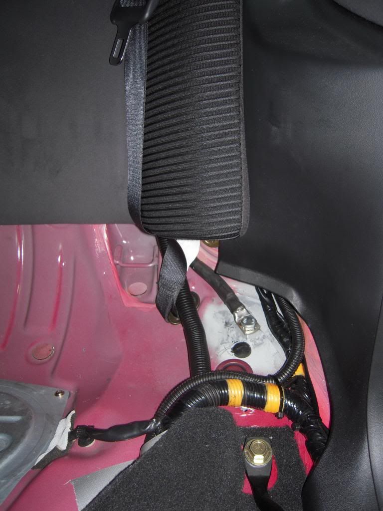
fourth photo is underneath back seat - earth mounting point, this is welded to the chassis. The positive cable is the one next to it covered with the protective plastic covering.
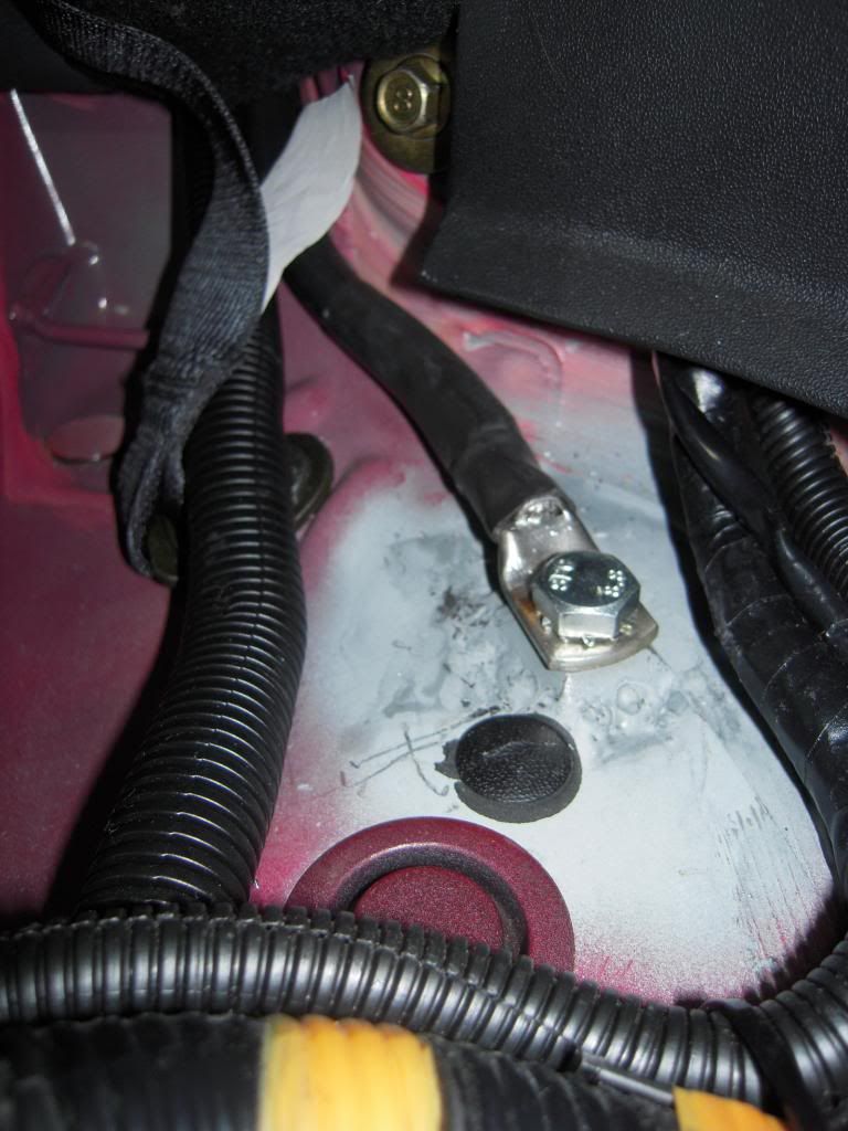
fifth photo is close up of earth mounting point. Welding in that area was differcult, so not the prettiest welding.
Six photo is in engine bay where you can see where the positive cable comes through the grommet in the firewall and tucks up behind the washer bottle.

Seventh photo is of custom made distribution block which has single 00gauge input and 1x 2 gauge ( to starter motor ) and 1x 4 gauge output ( to fuse box ).
Hope this is helpful for someone.
Rotaman
First photo of the boot with every thing in place
Second photo with carpet removed for access to battery etc.
Third photo is close up of custom made battery box and quick cut off.
fourth photo is underneath back seat - earth mounting point, this is welded to the chassis. The positive cable is the one next to it covered with the protective plastic covering.
fifth photo is close up of earth mounting point. Welding in that area was differcult, so not the prettiest welding.
Six photo is in engine bay where you can see where the positive cable comes through the grommet in the firewall and tucks up behind the washer bottle.
Seventh photo is of custom made distribution block which has single 00gauge input and 1x 2 gauge ( to starter motor ) and 1x 4 gauge output ( to fuse box ).
Hope this is helpful for someone.
Rotaman
Would you be so kind to share some more details and give some advice?
I'm planning to relocate my Odyssey 680 battery to the washer bottle location. I have a JDM gen1 RX-8.
I plan to redo the wiring for the positive loom.
So it would be:
BATTERY Positive----0gauge---->150 Amp FUSE----0gauge---->distribution block:
----2gauge---->60 amp fuse----2gauge-----> EPS
----2gauge---->100 amp fuse----2gauge----->Charging system
----2gauge---->100 amp fuse----2gauge-----> Fuse box
BATTERY Negative - to chassis.
1. What do you think, is it alright to use 2gauge wires after the distribution block? Maybe i need to use different wire?
2. What Amp fuse would you recommend straight after the Positive of the battery? 150 Amp is a good choice?
3. What kind of kill switch can you recommend for my setup?
Beforehand thankful, Nikolay.