
DIY: No Heat? Repair the Heater Control

 10-09-2008, 12:27 AM
#1
Registered User
Thread Starter

DIY: No Heat? Repair the Heater Control
No heat and only cooling, or only heat and no cooling, or erratic temperature control?
The temperature control **** seems to have quite a bit of issues for early RX8 owners where the system will cool only, and not provide heat despite the position of the control ****. This can also work in the opposite way, only heating and no cooling. After living with it for a season, I finally pulled the heater control unit out and repaired the circuit board. It was simple to repair and because I was going to have to pull the unit out anyway to replace it, it was not much extra work. The replacement unit (part FE01-61-190) retails for $350, some vendors on this site sell it for $240ish, and I hear there are some that sell used parts for $125ish. It is definitely covered under warranty for those lucky enough to be under warranty.
If you do not have heat, or only have heat, IMHO it is most likey the AC/heater control unit. This is the part which has the AC/heat control buttons and *****.
Easy Diagnosis:
The easiest way to verify this is to turn on the radio, press and hold the power on/off button and press and hold the scan-up button for a second (full second). The word "A/C TEMP" should appear on the left of the display and a number from 0 to 16 on the right. I suspect yours will have the number 0 (or 16 if heating only problem) displayed no matter where you turn the temperature control ****. If this is the case you could turn the temp. **** to full heat and see if it goes to 16 after pushing down or to the right on the ****.
In a working system, the number moves evenly in increments of 1, from 0 to 16 as you turn the temperature ****.
Easy Fix:
I was able to take mine out and solder 3 loose connections to fix it.
The beginning steps are the same as for any radio removal procedure. Instead of reinventing the wheel I would like to direct anyone to John Masone’s excellent DIY for radio removal at this DIY:
https://www.rx8club.com/series-i-do-yourself-forum-73/diy-radio-removal-add-aux-input-36001/
or directly linked here:
http://www.whatsmyip.org/ipodrx8/
The procedure is basically the same until page 7, second frame. Here is the modified step at that phase:

Removal of Heater Control Unit
I did not take pictures of the next step which is basically removing the cover on the temperature **** side of the control which requires a small screwdriver to three plastic clips on the perimeter of the cover. This will be evident when you get it in front of you. I stripped the circuit board down further than you may need to because I was also repairing cracked defrost (windshield and rear) buttons with superglue.
Then re-solder the 3 joints indicated in the next photos. A little bit of heat and just a little extra solder and they should be good to go.

Front of Heater Control Circuit Board

Front of Temperature Control **** (3 connections noted)
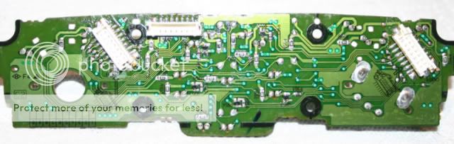
Back of Heater Control Circuit Board

Back of Heater Control ****

3 Bad Solder Joints (Note cracks) Prior to Re-soldering
I did the power-button/up scan combination to get the head unit to display the dial position and it now travels even increments from 0 to 16, instead of jumping from 0 to 16 when pushed like before. And the temperature control works perfectly.
Good luck.
The temperature control **** seems to have quite a bit of issues for early RX8 owners where the system will cool only, and not provide heat despite the position of the control ****. This can also work in the opposite way, only heating and no cooling. After living with it for a season, I finally pulled the heater control unit out and repaired the circuit board. It was simple to repair and because I was going to have to pull the unit out anyway to replace it, it was not much extra work. The replacement unit (part FE01-61-190) retails for $350, some vendors on this site sell it for $240ish, and I hear there are some that sell used parts for $125ish. It is definitely covered under warranty for those lucky enough to be under warranty.
If you do not have heat, or only have heat, IMHO it is most likey the AC/heater control unit. This is the part which has the AC/heat control buttons and *****.
Easy Diagnosis:
The easiest way to verify this is to turn on the radio, press and hold the power on/off button and press and hold the scan-up button for a second (full second). The word "A/C TEMP" should appear on the left of the display and a number from 0 to 16 on the right. I suspect yours will have the number 0 (or 16 if heating only problem) displayed no matter where you turn the temperature control ****. If this is the case you could turn the temp. **** to full heat and see if it goes to 16 after pushing down or to the right on the ****.
In a working system, the number moves evenly in increments of 1, from 0 to 16 as you turn the temperature ****.
Easy Fix:
I was able to take mine out and solder 3 loose connections to fix it.
The beginning steps are the same as for any radio removal procedure. Instead of reinventing the wheel I would like to direct anyone to John Masone’s excellent DIY for radio removal at this DIY:
https://www.rx8club.com/series-i-do-yourself-forum-73/diy-radio-removal-add-aux-input-36001/
or directly linked here:
http://www.whatsmyip.org/ipodrx8/
The procedure is basically the same until page 7, second frame. Here is the modified step at that phase:
Removal of Heater Control Unit
I did not take pictures of the next step which is basically removing the cover on the temperature **** side of the control which requires a small screwdriver to three plastic clips on the perimeter of the cover. This will be evident when you get it in front of you. I stripped the circuit board down further than you may need to because I was also repairing cracked defrost (windshield and rear) buttons with superglue.
Then re-solder the 3 joints indicated in the next photos. A little bit of heat and just a little extra solder and they should be good to go.
Front of Heater Control Circuit Board
Front of Temperature Control **** (3 connections noted)
Back of Heater Control Circuit Board
Back of Heater Control ****
3 Bad Solder Joints (Note cracks) Prior to Re-soldering
I did the power-button/up scan combination to get the head unit to display the dial position and it now travels even increments from 0 to 16, instead of jumping from 0 to 16 when pushed like before. And the temperature control works perfectly.
Good luck.
Last edited by Wingnut; 10-26-2008 at 12:04 AM. Reason: Larger attachments

The following 12 users liked this post by Wingnut:
Chuck56nAZ (11-17-2019),
dcfc3s (01-01-2021),
GA-Shinka-05 (08-08-2018),
hufflepuff (02-13-2022),
jes-13 (03-15-2018),
and 7 others liked this post.


 10-10-2008, 12:02 AM
#4
I made some poos
iTrader: (1)

Join Date: Sep 2005
Location: Pittsburgh, PA
Posts: 841
Likes: 0
Received 0 Likes
on
0 Posts
This is fantastic. I wish I knew it was this simple before I replaced my bad one.
Oh well, I guess I'll get the soldering iron out and repair the old one anyways, its always good to have spare parts.
Oh well, I guess I'll get the soldering iron out and repair the old one anyways, its always good to have spare parts.
 10-11-2008, 01:16 PM
#6
Green Machine

Join Date: May 2008
Location: Bothell, WA
Posts: 2
Likes: 0
Received 0 Likes
on
0 Posts
I just got done trying this, and it worked perfectly. The most annoying part for me was finding (yes finding !?!) the bolt to undo the radio.
After looking around under the steering column for half an hour or so and not quite being able to get my head in the right spot to see the bolt, I finally removed the metal part that goes across the bottom of the column (you can see it in the bottom picture on page 4 in the radio removal DIY). It is held on with 4 screws. With that out of the way, I was able to see the bolt and get at it much easier.
Also, the part about being careful about not dropping the bolt is important. I was being very careful right up until I dropped it into a bottomless pit.
10-12-2008, 04:43 AM
#7
Registered User

Join Date: Dec 2007
Posts: 15
Likes: 0
Received 0 Likes
on
0 Posts
Continuation of Wingnut's DIY
I just got done doing this today. Worked EXCELLENTLY. I'm posting up some additional tips and instructions to make this even easier.
Tip: When unscrewing the bolt behind the dash, make sure to put some sort of sticky, adhesive substance on your ratchet socket. I went ahead and put some electrical tape on mine, sticky side up. If you don't do this, your bolt will likely drop somewhere behind the carpet and be lost forever. Also, when putting the bolt back I recommend taping its rim to the ratchet socket. That way it will stick to the socket until it is locked in tight enough and you can just pull the socket off, with nothing falling.
Ok, from this point in Masone's guide til the beginning of Wingnut's DIY you should have no problem following the instructions...
Now, once you get the first picture posted by Wingnut, his last step mentions to unscrew 2 screws to get out the ac unit. It is actually 6 screws, two on upper unit, two on lower, and two below the unit, although you will likely figure this out just thought I'd put it in there for sake of completeness.
Anyway, after you have pulled out the unit, you will arrive at my first photo (attached below). Unclip the pieces using a small flathead screwdriver at the three locations indicated by the red circles. Also, loosen the wire bundle on the right from its hooks so that it can slide into the case later on (when pulling out the circuit board).
After this (as indicated in my second photo), flip the unit around and unscrew the center mode control by unscrewing the screws at the 4 red circles. Next, bend out the side portions (at the yellow circles) a bit to unlock the board from the plastic case. I recommend unmounting the left side first. When doing the right side, use a small flathead screwdriver to pry the wirebundle (indicated in my third photo) from its socket on the board. This allows the board to come out enough so that you can solder the joints.
Lastly, you should have access to the necessary joints (indicated in fourth photo) and you can resume following Wingnut's great DIY. The soldering was very easy - as Wingnut mentions - and I didn't have to remove the two wire bundles plugged into the board in picture 4, as I was able to get it to bend out far enough to easily work on it.
I hope this helps someone out! After you do it, you too should be:
 10-16-2008, 09:48 PM
#9
Registered User

Join Date: Mar 2004
Posts: 16
Likes: 0
Received 0 Likes
on
0 Posts
Thanks Wingnut. I thought I was screwed out of a few hundred dollars until I did a search. Took about half a day including having to pick up a soldering iron. Couldn've been simpler. Hopefully Mazda will make this a recallable issue. Sounds like this issue is showing that the circuit board has some defects.


 10-19-2008, 03:57 PM
#13
No means yes
iTrader: (1)

Join Date: Nov 2006
Location: Jersey City NJ
Posts: 1,507
Likes: 0
Received 0 Likes
on
0 Posts
That spring goes in the ashtray piece, on the back. I'll try to snap a picture when I do this fix...
10-19-2008, 05:24 PM
#14
White is purdy...

Join Date: Dec 2007
Location: Jersey Shore
Posts: 656
Likes: 0
Received 0 Likes
on
0 Posts
thank you very much. i'm going to do this next free saturday i have. probably next saturday. i'm under warranty but if i go to the dealer i'll likely lose my warranty for various things, so i'd rather just fix it myself.
10-19-2008, 06:02 PM
#15
Russian Mafia

Join Date: Jun 2008
Location: Louisville, KY
Posts: 128
Likes: 0
Received 0 Likes
on
0 Posts
Please do. I figured it went somewhere on the back to hold it and all, but could not figure out where exactly to put it.
 10-20-2008, 06:25 AM
#17
Registered User

Join Date: Oct 2008
Posts: 3
Likes: 0
Received 0 Likes
on
0 Posts
Wingnut - Thanks! Great instructions, links and pictures. Took about an hour an a half and saved $$$. Kudos!
IKoRTy - That is from the ashtray hinge. Mine came off as well and that side of the hinge decided to disintigrate. A well placed screw fixed the problem for me. It is a little harder to open/close now, but it beats buying a new one when I never use the dang thing.
IKoRTy - That is from the ashtray hinge. Mine came off as well and that side of the hinge decided to disintigrate. A well placed screw fixed the problem for me. It is a little harder to open/close now, but it beats buying a new one when I never use the dang thing.
10-20-2008, 09:27 AM
#19
No means yes
iTrader: (1)
Join Date: Nov 2006
Location: Jersey City NJ
Posts: 1,507
Likes: 0
Received 0 Likes
on
0 Posts
It goes on the back (left IIRC) ... Look for two little holes where the flat ends of the spring can go. One hole on the lid, one on the base.
I should be doing this fix over the weekend so I will snap a pic then
I should be doing this fix over the weekend so I will snap a pic then
10-20-2008, 03:04 PM
#20
White is purdy...
Join Date: Dec 2007
Location: Jersey Shore
Posts: 656
Likes: 0
Received 0 Likes
on
0 Posts
Hey CnnmnSchnpps, when during the weekend do you think you're gonna be doing this? I'm probably doing mine over the weekend as well. Maybe We could have a "Fix your heater" party with a bunch of the guys from the club
10-21-2008, 12:58 PM
#21
Registered User
Join Date: Oct 2008
Posts: 3
Likes: 0
Received 0 Likes
on
0 Posts
Looks like I have to do my wife's car over this weekend. I think she was waiting for me to experiment with my car before she trusted me with her's. Although her's is a little different as the temp setting keeps changing arbitrarily. I am hoping it is the same fix. I am up for the virtual party! Anyone want to come over and take care of that little bolt in the back for me??

 10-25-2008, 09:54 PM
#24
No means yes
iTrader: (1)
Join Date: Nov 2006
Location: Jersey City NJ
Posts: 1,507
Likes: 0
Received 0 Likes
on
0 Posts
Wingnut - Very nice DIY! Thanks a ton. It only took like an hour to do this fix. My soldering ain't pretty but it will do the job

Someone had previously attempted the radio removal on my car, since I had no retaining bolt, and the main harness connector on the back of the radio was mangled beyond recognition, so much so that I could not actually remove the radio...

-D
10-26-2008, 01:10 PM
#25
Registered User

Join Date: Oct 2008
Posts: 2
Likes: 0
Received 0 Likes
on
0 Posts
I want to thank everyone that posted tips on this...
Thank you, thank you, thank you!
I just finished doing my 2004 and the heat and cooling control now works like it is suppose to. Mine started acting up a little bit a year ago, but got real bad a few months ago. I had a dealer look at it a couple weeks ago, and they quoted me $800 to fix it and I believe they misdiagnoised the problem and were going to replace the A/C amplifier under the drivers side dash! Lucky for me they didn't have the parts, so I left with no bill.
The easy and sure diagnois with the "hold ON/OFF button and push SCAN up" gave me confidence this was the problem. And it also confirmed the fix before I even started up the car, just turned the key on and checked it.
The only bad part was my ash tray spring did pop out, and I wasted a half hour trying to put it back in. Then I noticed one of the holes was broken in half (not on the ash tray door, on the ash tray body. Is this caused when the ash tray is removed with the door open? Would it have helped to close the door when removing it? I don't know, but I am happy the heat/cool works again. I was able to super glue the broken bit, and then put 2-part epoxy over it for more strength. The ash tray snaps open/closed correctly now, I'll see for how long.
Took 2 hours, including my wasted 1/2 hour with the ash tray spring. Somebody more familiar with the electrical connectors could do it faster. It did go back together easier than taking it apart.
Thanks to all.
Last edited by RX8Jim; 10-26-2008 at 07:46 PM.