
Emanage Ultimate Turbo Upgrade Kit Findings
 10-02-2007, 03:38 PM
#51
Guest
Posts: n/a
It may not be the all around "perfect" way to tune in vacuum in these rpm ranges, but for the time being, it works well and the ignition timing is no longer holding anyone back with this engine management.

 03-10-2008, 11:21 AM
#53
No means yes
iTrader: (1)

Join Date: Nov 2006
Location: Jersey City NJ
Posts: 1,507
Likes: 0
Received 0 Likes
on
0 Posts
- The "coming from/going to" terms are a little confusing. I'm assuming that for injection and ignition, the EMU "inputs" come from the PCM and the EMU "outputs" go to the wiring harness. For the MAF sensor EMU input = wiring harness, EMU output = PCM. Is that correct?
- Water temp - what's the deal with this? You mentioned something about it not working, but I couldn't find any details.
Thanks!
-D
(edited to remove questions that got answered by more reading
 )
)
Last edited by CnnmnSchnpps; 03-24-2008 at 12:38 PM.
03-12-2008, 10:37 PM
#54
No means yes
iTrader: (1)
Join Date: Nov 2006
Location: Jersey City NJ
Posts: 1,507
Likes: 0
Received 0 Likes
on
0 Posts
Ok I think I'm getting closer to understanding how this EMU thing works.. If I understand correctly, the sub injector channels allow you to run injectors at points where the PCM would not be turning the P2s on at all, so you have a fuel source that you have 100% control over, over the entire RPM range.
For my purposes, I want to get it running first with the exact same maps as stock. Do you see any problems with wiring the injectors to;
CH1 - P +/-
Ch2 - P +/-
Ch3 - S +/-
Ch4 - S +/-
Ch5 - P2 +/-
Ch6 - P2 +/-
This way I should be able to 0 out all the maps and just run "stock", right?
As an aside, why the hell are the P2s called "primary 2"?? Is "tertiary" that difficult to pronounce??
03-24-2008, 12:35 PM
#57
No means yes
iTrader: (1)
Join Date: Nov 2006
Location: Jersey City NJ
Posts: 1,507
Likes: 0
Received 0 Likes
on
0 Posts
A couple more random questions
- Taking apart the EMU connectors is a PITA! I got the white back that holds in the wires out of the gray plug, but the individual wires (with the crimped-on connectors) won't come out! I need to take it out to see what kind to buy (I need to add wires for the extra injector channels for +/-) I seem to remember a post around here somewhere explaining how to take them out, but I can't find it anymore
  Could someone either tell me how to take these buggers out, or what kind to buy?
- Does anyone have any experience with the multi switch system (MSS). I have seen hints here and there of its capability, and that it has some integration with the EMU (via an option port), but I couldn't find any details... I want to see if it can be used to switch between maps based on a voltage trigger (nitrous system activation)
Thanks,
-Dmitri
- Taking apart the EMU connectors is a PITA! I got the white back that holds in the wires out of the gray plug, but the individual wires (with the crimped-on connectors) won't come out!
I need to take it out to see what kind to buy (I need to add wires for the extra injector channels for +/-) I seem to remember a post around here somewhere explaining how to take them out, but I can't find it anymore Could someone either tell me how to take these buggers out, or what kind to buy?- Does anyone have any experience with the multi switch system (MSS). I have seen hints here and there of its capability, and that it has some integration with the EMU (via an option port), but I couldn't find any details... I want to see if it can be used to switch between maps based on a voltage trigger (nitrous system activation)
Thanks,
-Dmitri
03-24-2008, 01:22 PM
#58
You just need a flat-blade jeweler's screw driver.
You don't take the white "block" out, you just slide it up by disengaging the "teeth" on the sides a bit.
One that is done, you insert the screwdriver into the trapezoidal slot above each pins entry point on the front of the connector about 3mm, pointing somewhat downwards until it engages the tang and then simultaneously lift and pull the wire from the back.
Not to rub it in your face, but I can typically remove all 40+ wires from the three connectors in about 40 - 90 seconds.
03-24-2008, 02:08 PM
#59
No means yes
iTrader: (1)
Join Date: Nov 2006
Location: Jersey City NJ
Posts: 1,507
Likes: 0
Received 0 Likes
on
0 Posts
Thanks for your help! 2 seconds per sounds reasonable once you find the "trick".. You wanna race? 
As for the white plate, I took it off completely just so it wouldn't lock back up on me while I was messing with the rest of the wires.. Once I get the hang of it I will do as you say, just slide it up
As for the white plate, I took it off completely just so it wouldn't lock back up on me while I was messing with the rest of the wires.. Once I get the hang of it I will do as you say, just slide it up
 07-20-2008, 01:47 AM
#62
I'm checking through a second-hand emu and it has a number of connectors and a broken wire or two.
it appears to be wired as Tdiddy listed.
for some reason the piggybacked crank-sensor wire (brown) pin 33 connector C has a bullet connector on it so it can be disconnected? is this normal?
then pin 14 connector D has a bullet connector but is disconnected. there is nothing to plug it into apart from the water temp signal (2K pcm) which is straight through but connected with a bullet style connector.
I want to leave the PCM controlling all the intake ports and valves. especially the auxiliary port valve.
(SSS) 1D is straight through on the pcm.
(SSV)1L is intercepted at the PCM ( this might be an internal break as it looks like a piggy back connection) with pin 44 connector C connected to the loom side and a severed yellow wire connected to the pcm side. it looks like this yellow wire was connected to +B via a resistor. ?
(edit)aux port mod done
I can see why you need to re-wire the injectors to adding and subtracting for a N/A set-up and if you use larger injectors for a turbo but what if you use the std injectors for a forced induction set-up? I can see that I would need to trim fuel?
Last edited by rotarenvy; 08-01-2008 at 04:06 AM.
08-19-2008, 07:13 PM
#63
Yeay Boosted!

Join Date: Oct 2007
Location: New Hampshire
Posts: 271
Likes: 0
Received 0 Likes
on
0 Posts
Another threadsurrection.
Jumper Settings
JP1 - Injector Input/Output CH-1 = OPEN (IN/OUT)1
JP2 - Injector Input/Output CH-2 = OPEN (IN/OUT)1
JP3 - Injector Input/Output CH-3 = OPEN (IN/OUT)1
JP4 - Injector Input/Output CH-4 = OPEN (IN/OUT)1
JP5 - Injector Input/Output CH-5 = OPEN (IN/OUT)1
JP6 - Injector Input/Output CH-6 = OPEN (IN/OUT)1
JP7 - Ignition Input = 1-2 (Normal)
JP8 - Ignition Output = 2-3 (12 volt)2
JP9 - Airflow Signal Input/Output = Open (Normal)
JP10 - Airflow Signal Input 2 = 2-3 (VTEC OUT)
JP11 - OPTION 1 = Open (Normal)
JP12 - OPTION 2 = Open (Normal)
JP13 - Knock Signal Input 1/Water Temp Input = 1-2 (Pull Up)
JP14 - Knock Signal Input 2/Water Temp Input = 1-2 (Pull Up)
JP15 - RPM Signal Input = 1-2 (Normal Input)
JP16 - Frequency Input/VTEC Input = 1-2 (VTEC IN)
JP17 - Frequency Output/VTM Output = OPEN (VTM)
JP18 - Injector Input/Output Signal CH1~6 = OPEN (IN/OUT)
JP19 - Injector Signal CH-A = 1-2 (I/J, Sub I/J, NVCS, Relay(-))
JP20 - Injector Signal CH-B = 1-2 (I/J, Sub I/J, NVCS, Relay(-))
Wire Connections:
Ultimate Connector A (12 Pin)
Pin #3 - Ignition Input Signal CH-4 (intercepts) goes to PCM Pin #2Z - Rear Leading Ignition Coil 3
Pin #10 - Ignition Input Signal CH-3 (intercepts) goes to PCM Pin #2AA - Front Leading Ignition Coil 3
Pin #4 - Ignition Input Signal CH-2 (intercepts) goes to PCM Pin #2AC - Rear Trailing Ignition Coil 3
Pin #5 - Ignition Input Signal CH-1 (intercepts) goes to PCM Pin #2AD - Front Trailing Ignition Coil 3
Pin #8 - Ignition Output Signal CH-4 (intercepts) comes from PCM Pin #2Z - Rear Leading Ignition Coil 3
Pin #9 - Ignition Output Signal CH-3 (intercepts) comes from PCM Pin #2AA - Front Leading Ignition Coil 3
Pin #11 - Ignition Output Signal CH-2 (intercepts) comes from PCM Pin #2AC - Rear Trailing Ignition Coil 3
Pin #12 - Ignition Output Signal CH-1 (intercepts) comes from PCM Pin #2AD - Front Trailing Ignition Coil 3
Ultimate Connector B (18 pin)
Pin #15 – Airflow (voltage) Input (intercepts) comes from PCM Pin #5N – MAF
Pin #22 – Airflow (voltage) Output (intercepts) goes to PCM Pin #5N – MAF
Pin #16 - Throttle Pos. Sensor Input (piggybacks) comes from/goes to PCM Pin #5F - Accelerator
Pin #17 – Injector Input Signal CH-1 comes from PCM Pin #2M – Front Primary Injector (intercepted) 4
Pin #18 – Injector Input Signal CH-2 comes from PCM Pin #2J – Rear Primary Injector (intercepted) 4
Pin #19 – Injector Input Signal CH-3 comes from PCM Pin #2G – Front Secondary Injector (intercepted) 4
Pin #20 – Injector Input Signal CH-4 comes from PCM Pin #2D – Rear Secondary Injector (intercepted) 4
Pin #24 – ECU Ground (piggybacks) comes from PCM Pin #4J – PCM EFI Ground
Pin #25 – ECU (Ignition) Power (piggybacks) comes from PCM Pin #4Q – PCM EFI Power
Pin #30 – Injector Ground (Sensor) goes to (piggybacks) PCM Pin #4A – Injector Ground
Ultimate Connector C (14 pin)
Pin #32 - Knock Signal 1/Water Temp Signal
Pin #33 – Crank Angle Signal Input (piggybacks) comes from/goes to PCM Pin #2U – Eccentric Shaft Position
Pin #43 – Injector Output Signal CH-5 goes to PCM Pin #3A – Front Primary 2 Injector 7
Pin #44 – Injector Output Signal CH-6 goes to PCM Pin #3D – Rear Primary 2 Injector 7
Pin #34 - Injector Output Signal CH-1 goes to PCM Pin #2M – Front Primary Injector (intercepted) 7
Pin #35 - Injector Output Signal CH-2 goes to PCM Pin #2J – Rear Primary Injector (intercepted) 7
Pin #36 - Injector Output Signal CH-3 goes to PCM Pin #2G – Front Secondary Injector (intercepted) 7
Pin #42 - Injector Output Signal CH-4 goes to PCM Pin #2D – Rear Secondary Injector (intercepted) 7
Ultimate Dongle
Lt.Blue Wire #1 – (piggybacks) comes from/goes to PCM Pin #2B – WBO2S 8
Lt.Blue Wire #2 = (piggybacks) comes from/goes to PCM Pin #2C – WBO2S 8
Green Wire – (piggybacks) comes from/goes to Ultimate Connector B Pin #26 (PCM Pin #4O)
Red Wire – (piggybacks) comes from/goes to PCM Pin #4Q – PCM EFI Power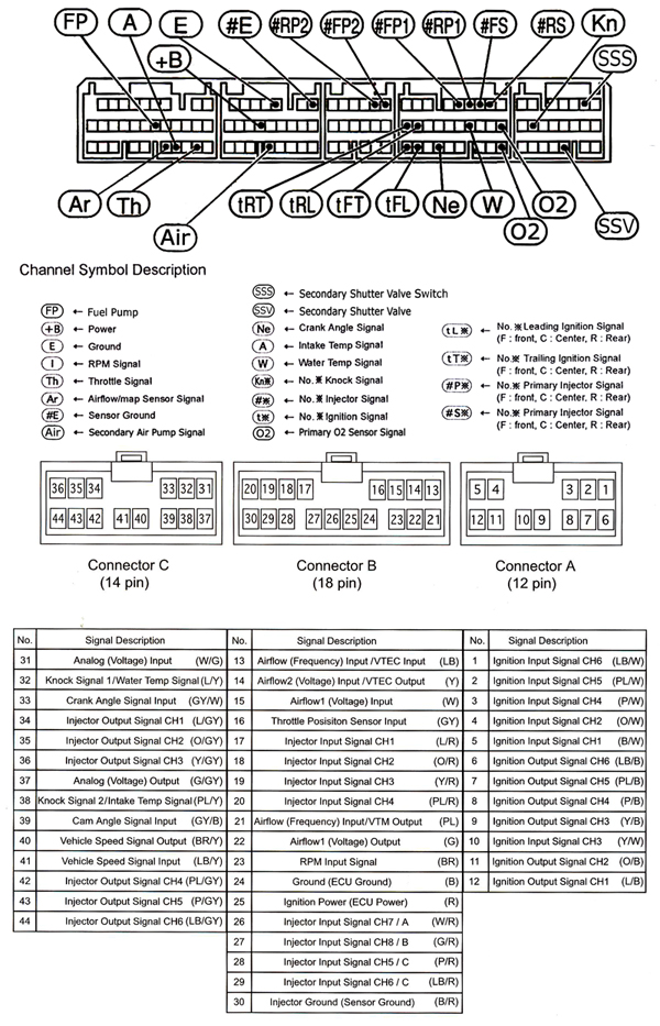
Here is the wiring that I use on my EMU.
See notes for explanations for importance of emphasized connections.
See notes for explanations for importance of emphasized connections.
Jumper Settings
JP1 - Injector Input/Output CH-1 = OPEN (IN/OUT)1
JP2 - Injector Input/Output CH-2 = OPEN (IN/OUT)1
JP3 - Injector Input/Output CH-3 = OPEN (IN/OUT)1
JP4 - Injector Input/Output CH-4 = OPEN (IN/OUT)1
JP5 - Injector Input/Output CH-5 = OPEN (IN/OUT)1
JP6 - Injector Input/Output CH-6 = OPEN (IN/OUT)1
JP7 - Ignition Input = 1-2 (Normal)
JP8 - Ignition Output = 2-3 (12 volt)2
JP9 - Airflow Signal Input/Output = Open (Normal)
JP10 - Airflow Signal Input 2 = 2-3 (VTEC OUT)
JP11 - OPTION 1 = Open (Normal)
JP12 - OPTION 2 = Open (Normal)
JP13 - Knock Signal Input 1/Water Temp Input = 1-2 (Pull Up)
JP14 - Knock Signal Input 2/Water Temp Input = 1-2 (Pull Up)
JP15 - RPM Signal Input = 1-2 (Normal Input)
JP16 - Frequency Input/VTEC Input = 1-2 (VTEC IN)
JP17 - Frequency Output/VTM Output = OPEN (VTM)
JP18 - Injector Input/Output Signal CH1~6 = OPEN (IN/OUT)
JP19 - Injector Signal CH-A = 1-2 (I/J, Sub I/J, NVCS, Relay(-))
JP20 - Injector Signal CH-B = 1-2 (I/J, Sub I/J, NVCS, Relay(-))
Wire Connections:
Ultimate Connector A (12 Pin)
Pin #3 - Ignition Input Signal CH-4 (intercepts) goes to PCM Pin #2Z - Rear Leading Ignition Coil 3
Pin #10 - Ignition Input Signal CH-3 (intercepts) goes to PCM Pin #2AA - Front Leading Ignition Coil 3
Pin #4 - Ignition Input Signal CH-2 (intercepts) goes to PCM Pin #2AC - Rear Trailing Ignition Coil 3
Pin #5 - Ignition Input Signal CH-1 (intercepts) goes to PCM Pin #2AD - Front Trailing Ignition Coil 3
Pin #8 - Ignition Output Signal CH-4 (intercepts) comes from PCM Pin #2Z - Rear Leading Ignition Coil 3
Pin #9 - Ignition Output Signal CH-3 (intercepts) comes from PCM Pin #2AA - Front Leading Ignition Coil 3
Pin #11 - Ignition Output Signal CH-2 (intercepts) comes from PCM Pin #2AC - Rear Trailing Ignition Coil 3
Pin #12 - Ignition Output Signal CH-1 (intercepts) comes from PCM Pin #2AD - Front Trailing Ignition Coil 3
Ultimate Connector B (18 pin)
Pin #15 – Airflow (voltage) Input (intercepts) comes from PCM Pin #5N – MAF
Pin #22 – Airflow (voltage) Output (intercepts) goes to PCM Pin #5N – MAF
Pin #16 - Throttle Pos. Sensor Input (piggybacks) comes from/goes to PCM Pin #5F - Accelerator
Pin #17 – Injector Input Signal CH-1 comes from PCM Pin #2M – Front Primary Injector (intercepted) 4
Pin #18 – Injector Input Signal CH-2 comes from PCM Pin #2J – Rear Primary Injector (intercepted) 4
Pin #19 – Injector Input Signal CH-3 comes from PCM Pin #2G – Front Secondary Injector (intercepted) 4
Pin #20 – Injector Input Signal CH-4 comes from PCM Pin #2D – Rear Secondary Injector (intercepted) 4
Pin #24 – ECU Ground (piggybacks) comes from PCM Pin #4J – PCM EFI Ground
Pin #25 – ECU (Ignition) Power (piggybacks) comes from PCM Pin #4Q – PCM EFI Power
- This wire also connects to the Dongle Red Wire as noted below
- This wire also goes to PCM Pin #1L through a 5k ohm resistor – Secondary Shutter Valve
Pin #26 – Injector Output Signal CH-7/A goes to (piggybacks) PCM Pin #4O – Secondary Air Injection Pump (a diode is inserted on the PCM side) 5- This wire also goes to PCM Pin #1L through a 5k ohm resistor – Secondary Shutter Valve
- This wire also connects to the Dongle Green Wire
Pin #27 – Injector Output Signal CH-8/B goes to (piggybacks) PCM Pin #1L – Secondary Shutter Valve (a diode is inserted on the PCM side) 6Pin #30 – Injector Ground (Sensor) goes to (piggybacks) PCM Pin #4A – Injector Ground
Ultimate Connector C (14 pin)
Pin #32 - Knock Signal 1/Water Temp Signal
Pin #33 – Crank Angle Signal Input (piggybacks) comes from/goes to PCM Pin #2U – Eccentric Shaft Position
Pin #43 – Injector Output Signal CH-5 goes to PCM Pin #3A – Front Primary 2 Injector 7
Pin #44 – Injector Output Signal CH-6 goes to PCM Pin #3D – Rear Primary 2 Injector 7
Pin #34 - Injector Output Signal CH-1 goes to PCM Pin #2M – Front Primary Injector (intercepted) 7
Pin #35 - Injector Output Signal CH-2 goes to PCM Pin #2J – Rear Primary Injector (intercepted) 7
Pin #36 - Injector Output Signal CH-3 goes to PCM Pin #2G – Front Secondary Injector (intercepted) 7
Pin #42 - Injector Output Signal CH-4 goes to PCM Pin #2D – Rear Secondary Injector (intercepted) 7
Ultimate Dongle
Lt.Blue Wire #1 – (piggybacks) comes from/goes to PCM Pin #2B – WBO2S 8
Lt.Blue Wire #2 = (piggybacks) comes from/goes to PCM Pin #2C – WBO2S 8
Green Wire – (piggybacks) comes from/goes to Ultimate Connector B Pin #26 (PCM Pin #4O)
Red Wire – (piggybacks) comes from/goes to PCM Pin #4Q – PCM EFI Power
1 The injection signals should be switched to +/- so that fuel can be trimmed as well as added. This is also a more stable way to wire the injectors, as noted in points 4 and 7.
2 The OP noted that the ignition output is set to 12v. The Ignition on the RX-8 is 5v, so I wasn''t sure why this would be set to 12v.
However, after experimentation, I deduced that the ignition module that is installed on the GReddy board must trim the amplitude of the output signal to mirror the input signal, regardless of this setting.
3 This is the proper order for the ignition wiring as per the installation manual. The OP noted that there was some "crossing" of the ignition lines. I don't have an acceptable theory as to why this would be, but wiring it "correctly" yields proper results.
4 Since we are wiring the injectors as "intercepted" rather than "piggybacked", the wiring for all of the injector lines is changed. Also, I am controlling the Primary 2 injectors as independent sub-injectors rather than "piggybacking" the secondaries as the kit comes wired.
5 Since I am intercepting the injector signals, the NCVS (relay) outputs should be driven by the connector "B" outputs. These are labeled "A" & "B" in the manual.
6 Same as 5
7 Since I am intercepting the injector signals, the injector outputs on connector "C" must be utilized. Note that the sub-injector outputs are now on this connector rather than connector "B" as noted in 5 & 6 above.
8 For some reason, the OP noted that these wires were attached to some other pins. I'm not sure how that could be in his case, but this is how it should be wired and this is how all of the EMU upgrade kit harnesses I have seen are wired. It simply won't work any other way as this is the dongle that spoofs the front O2 sensor.
Question, are pins 43 and 44 piggybacked or intercepted? you didn't mention it like the others.
Ultimate Connector C (14 pin)
Pin #32 - Knock Signal 1/Water Temp Signal
Pin #33 – Crank Angle Signal Input (piggybacks) comes from/goes to PCM Pin #2U – Eccentric Shaft Position
Pin #43 – Injector Output Signal CH-5 goes to PCM Pin #3A – Front Primary 2 Injector 7
Pin #44 – Injector Output Signal CH-6 goes to PCM Pin #3D – Rear Primary 2 Injector 7
Pin #34 - Injector Output Signal CH-1 goes to PCM Pin #2M – Front Primary Injector (intercepted) 7
Pin #35 - Injector Output Signal CH-2 goes to PCM Pin #2J – Rear Primary Injector (intercepted) 7
Pin #36 - Injector Output Signal CH-3 goes to PCM Pin #2G – Front Secondary Injector (intercepted) 7
Pin #42 - Injector Output Signal CH-4 goes to PCM Pin #2D – Rear Secondary Injector (intercepted) 7
08-19-2008, 08:08 PM
#65
Yeay Boosted!
Join Date: Oct 2007
Location: New Hampshire
Posts: 271
Likes: 0
Received 0 Likes
on
0 Posts
Sorry I think I understand, just don't want to blow stuff up..
" I am controlling the Primary 2 injectors as independent sub-injectors rather than "piggybacking" the secondaries as the kit comes wired."
so basically the greddy is controlling the P2. so I would cut them off from the ecu and wire directly to the greddy. I think that's what your saying.
so the output of #3A and #3D go to the greddy, and the Input side of #3A and #3D doesn't go anywhere..
09-07-2008, 01:35 AM
#68
zeroing the maps with std emu wiring drivable?
the only wiring change I have made is the AUX port mod.
I not trying to tune NA I just want to drive around.
can I zero the maps and run around NA?
I not trying to tune NA I just want to drive around.
can I zero the maps and run around NA?
 09-10-2008, 04:00 AM
#71
I have a zeroed map apart from the nvcs map which is set to off at all points under 0 kpa. I'm only driving very lightly under 3krpm and vacuum under 0 kpa. although it may get to 0 at some points with aggressive throttle movements.
I'm getting P0661 the SSV code and the check engine light.
my EMU was secondhand and their was a broken wire attached to the +ve and 1L. I read MM's wiring and he said it was connected through a 5K ohm resistor. so I put a 5K resistor there.
any suggestions?
I'm getting P0661 the SSV code and the check engine light.
my EMU was secondhand and their was a broken wire attached to the +ve and 1L. I read MM's wiring and he said it was connected through a 5K ohm resistor. so I put a 5K resistor there.
any suggestions?
09-10-2008, 07:21 PM
#72
Yeay Boosted!
Join Date: Oct 2007
Location: New Hampshire
Posts: 271
Likes: 0
Received 0 Likes
on
0 Posts
no, it comes from greddy with the 5k resistor already installed. it should be under the heatshrink tubing.. it's really small. you shouldn't have to put another resitor in there.
09-11-2008, 05:12 AM
#73
thanks marcux. there is only one resistor. I replaced the missing 5K resistor to repair my harness since it was damaged.
I'm guessing my problem is a broken joint the diode on the 1L line but wont be able to check it out until the weekend.
edit
yep it was the diode. you will never catch a manufacturer using resistors and diodes like this for this reason.
I'm guessing my problem is a broken joint the diode on the 1L line but wont be able to check it out until the weekend.
edit
yep it was the diode. you will never catch a manufacturer using resistors and diodes like this for this reason.
Last edited by rotarenvy; 09-12-2008 at 10:51 PM. Reason: confirming broken loom
12-18-2008, 11:13 AM
#74
Registered User

Join Date: Dec 2006
Posts: 255
Likes: 0
Received 0 Likes
on
0 Posts
Hey Jeff@Mazdamaniac
i got my EMU from a AT RE-AMEMIYA turbo kit hence i need to rewire everything, i will rewire the emu according to the diagram you list and the jumper set to what you mentioned.
Which firmware/software ver shd i use to tune it and anyone got a base map for 0.4bar for the greddy kit using this wiring scheme ?
Also there is 2 dongers included in the emu kit. one is a o2 related donger and i don't know what the other is for but there are wirings tapping on to the crank +ve and -ve
