When you click on links to various merchants on this site and make a purchase, this can result in this site earning a commission. Affiliate programs and affiliations include, but are not limited to, the eBay Partner Network.
While my knowledge is still growing, I'd suggest checking out my thread. I wrote out Kane's method of tuning from his video recordings. In my first post there is a spoiler with my plan to follow what Kane went over. It is fairly straight forward and you could probably be done within a day if you wanted. I had several vacuum leaks at idle I had to fix. Recently when I got time to do higher rpm testing I had found that my Tach was not reading anywhere close to what the ECU read in high rpm.
On the Rx8 since we have the variable intake valves and staged fuel injectors you may find it easier to climb your way up the rpm ranges by these stages.
Starting with idle tuning can help weed out potential errors like vacuum leaks. Which would throw off any tuning you do.
Thanks for your answer. I'll acctually fog-test my intake also to see if there are any provlems leak-wise. A LTFT of ~10 suggests so... Still I think this should not be a major issue in the high rpm and load range as a small leak should not deliver a significant amount of additional air in these situations. Still I'd like to make sure there is non of course...
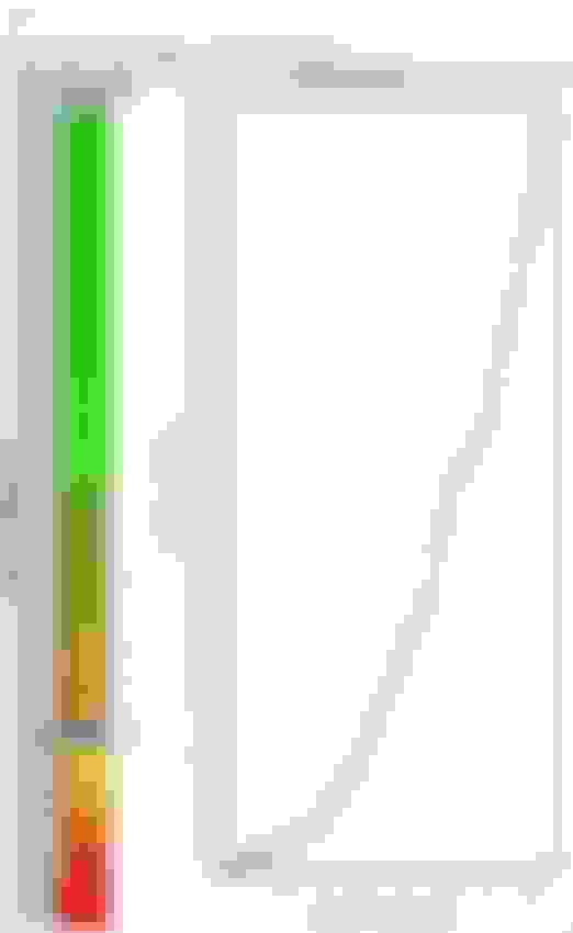
I logged fuel trims from 2000-4500rpm steady state and from there on logged OL / WOT aiming for fuel trims. I already posted the resultant curve and was interessted if it is unusual to see a result that look uncontentious..
I also plotted the suggetsted MAF correction (that corrensponds directly to the amount the acutyl AFRS are off compared to the target and it seems that there are certain lean spots in the rpm band.
There is one at about 4000rpm that could be the SSV switching, the last on at 7250 the VDI and another two in between (maybe APV at 6000rpm+ the one at 5500 I have no idea). The question is now, if I can really get rid of this by just adjusting the MAF scale. I see a ponntal problem as the swichting of the valves ocure at fixed rpm value (not SSV), butI can only adjust a g/sec scale. So when air desity is high (cold /high pressure), the g/sec value will be different at a certain rpm than with low air desity (hot/low pressure). So I might scale that away but will find myself in a problemetic situation when ambient conditions are different as the g/sec point shifts through the rpm band. I will work myself through your thread anyway! Thanks for the hint.
I also watched Kane's videos, in reality I thinks it's much harder to find trends here. In my case I have a LTFT at idle of ~10, fuel trims are then close to 0 until reaching 4000rpm. In OL corrections fluctuate from 0-20% where 0 is reached only in the very last part of the rpm range (above a bit more than 7500rpm).
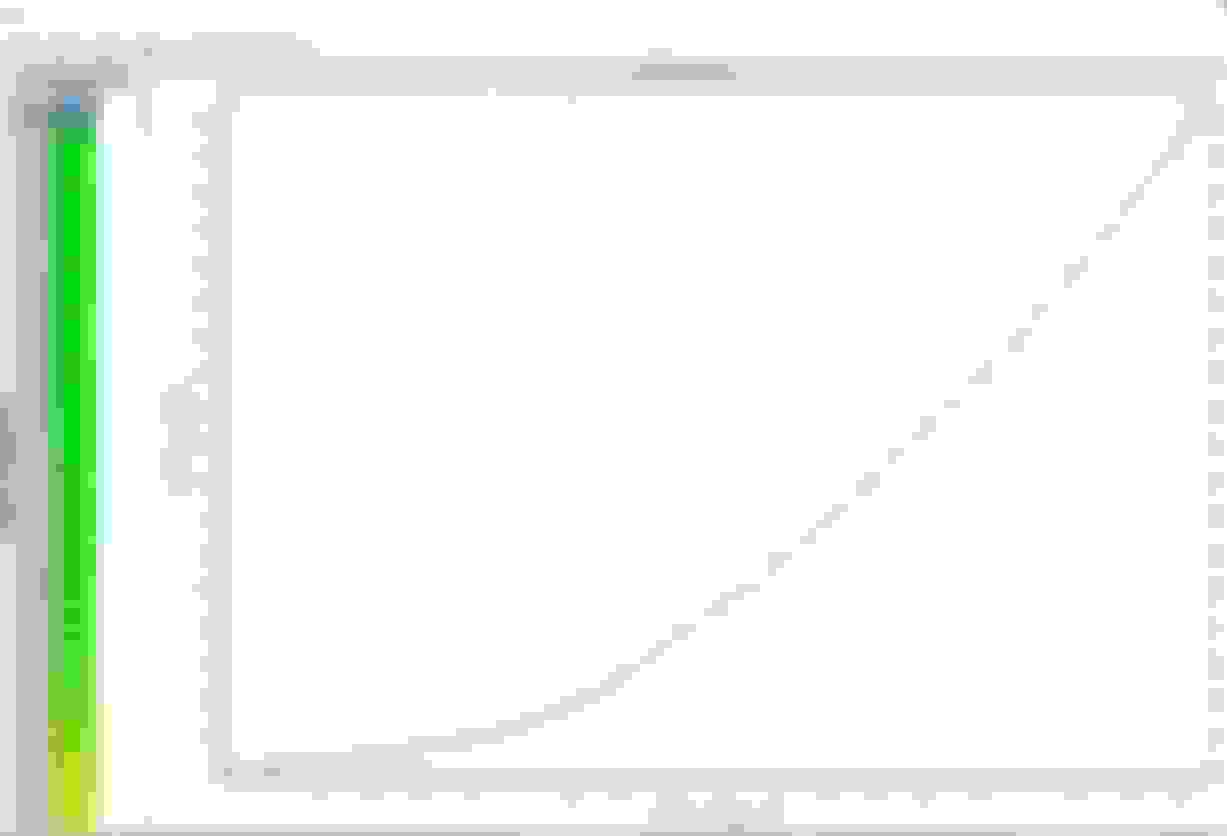
I made another loggin run, also logging the position of the SSV and VDI this time. The resultant MAF curve looks like this:
So correcting by target AFR ca. measured AFR, the MAF value for 3,125V is lower than the value for 3,008V. From the logs I can see, that the SSV came into play when the MAF-sensor was reading 2,89V.There is another plateau (not as dramativ as the first one) in the area of 3,6-3,7V, the VDI kicked in at 3,66V. So I guess its pretty safe to assume, that the AFRs in these areas are not off because the MAF is wrongly scaled, but the switching of SSV and later VDI changes the situation in the intake in a way the engine runs lean in this area.
Now I could just put 2 plateaus in the MAF curve but the problem is, that switching of the valves is not diretly related to a MAF value, but to a rpm value (plus load as I remember in case of the SSV). So in different driving conditions this will not help but rather bring the AFRs off again. Has anyone solved the problem of the intake valve switching by other means than chaging the MAF curve in a absurd way? Is this a situation to have a look on the ve fuel map? Or do you just life with not hitting AFRs in the 2 spots..?
Yes the problem has been solved many years ago ...by recognising that all the valves affect afrs and adjusting the fuel tables to minimise that effect. Not being anally retentive does wonders also.
Scaling the maf curve is totally the wrong way to go about it, and you have stated above why that is the case.
Ok, so I smooth out the MAF curve and than choose a AFR target in the OL fuel map that results in amn actual AFR I'd like to see in the rpm/load range where the valves are working, correct?
Ok, so I smooth out the MAF curve and than choose a AFR target in the OL fuel map that results in amn actual AFR I'd like to see in the rpm/load range where the valves are working, correct?
Sounds about right . When I'm tuning boosted engines I can't afford to get too caught up in getting absolute accuracy everywhere. The key is to adjust the things that make the most sense to adjust, such that afrs in the tables are close to actual afrs. Getting it close like that means for example : if afr on the table says 11.5 and you are getting 11.8 in reality but want 11.1 ..... you should be able to take 0.7 off 11.5 and get near as dammit 11.1.
Trying to get everything to line up exactly everywhere on the map is an exercise in futility because basically .....it's impossible.
maf scale , injector scale , injector latency, Ve table, fuel maps , max. calc load map, fuel enrich map, can all affect final AFR . The key to a good tune is recognising which one of those makes the most sense to adjust. When you have gone too far on one of those you should be thinking "what is wrong elsewhere that is causing me to have to skew this beyond what is a logical value". It could be in the tune or something wrong mechanically.
When I'm tuning a stock engine on a stock intake with stock injectors ...if things aren't lining up the way they should I know with 99% certainty that the issue is mechanical and I shouldn't be adjusting the tune before fixing the issue.
Tip : if you didn't know this already it will save you a ton of time : adjust ALL fuel maps to be identical. There is no such thing as 1-2, 3-4, 5-6 fuel maps . Yes more than one fuel map is utilised by the ECU but they are not by gear as labelled.
Sounds about right . When I'm tuning boosted engines I can't afford to get too caught up in getting absolute accuracy everywhere. The key is to adjust the things that make the most sense to adjust, such that afrs in the tables are close to actual afrs. Getting it close like that means for example : if afr on the table says 11.5 and you are getting 11.8 in reality but want 11.1 ..... you should be able to take 0.7 off 11.5 and get near as dammit 11.1.
Trying to get everything to line up exactly everywhere on the map is an exercise in futility because basically .....it's impossible.
maf scale , injector scale , injector latency, Ve table, fuel maps , max. calc load map, fuel enrich map, can all affect final AFR . The key to a good tune is recognising which one of those makes the most sense to adjust. When you have gone too far on one of those you should be thinking "what is wrong elsewhere that is causing me to have to skew this beyond what is a logical value". It could be in the tune or something wrong mechanically.
When I'm tuning a stock engine on a stock intake with stock injectors ...if things aren't lining up the way they should I know with 99% certainty that the issue is mechanical and I shouldn't be adjusting the tune before fixing the issue.
I think I already understood there are much too many variables involed in this procees. Finding the 100% solution is neither possible nor necessary. What makes it even harder is, that there are few experts around willing to share their knowledge and if someone does, threre are many different approaches on the same topic and as a beginner it is hardly possilbe to judge which is right for me. Most peolpe in this forum don't touch the injectors, some even say it's a bad idea. There are also posts to find in the www telling me not to scale the MAF but only to adjust fuel to hit my target...
Anyway, I'm glad there are some people around here willing to share knowlegde. I smoothed my curve now and will do some logging with that curve in the next days or weeks. To smooth the curve I fitted some curves over my data and replaced values that obviously looked off with values calculated from those functions.
Of course there might be problems I do not see as I have no experience, maybe there still is a small vacuum leak, I'll smoke test the intake and exhaust when I get the chance. btw. engine and injectors are stock. Intake is RB RAM Air duct connected to stock Airbox, so not too fare away from stock.
Thanks for the hint with the OL fuel maps. I just guessed they work for gears as they are titled this way in mazdaedit, but I will just use the same data for all 3 then, I guess the same is true for ignition timing? Is it known Ehen the ECU uses which map?
Maybe you can give me another hint for CL. For logging I filled all OL maps with a fixed value of 11,8 as target AFR. This worked pretty well and I could verify that what I did before worked quite well (using a normal table and interpolating target AFRs from there with rpm and load as input). I was suprised to see that in CL the ECU commanded AFRs very close to 14,7 also with this map! There are these CL fuel correction tables and I found a thread here that told this is a correction on the values from the OL table (e.g. if the CL table reads -0,1 and the OL table 14,7 the commanded AFR would be 14,7*(1-0,1)=13,23.
I can not confirm this as setting all values in OL to 11,8 and not changing the CL corrections tables values as high as 14,7 should not be possible.
Timing , make all the leading maps the same . And make the trailing maps the same.
The CL map : positive numbers remove fuel , negative numbers add fuel . The max. value you can put in there (that does anything) is plus or minus 0.030 which will change AFR by approx. 1.0 . The OL maps do nothing in closed loop
yes ..... I'm sure there is a map that changes that value which we don't have access to.
Thank you Brettus, I understand a lot more now and MAF scali looks pretty good now. There is a rpm range I'm running a little rich after smoothening out the MAF curve which I compensated by setting target AFRs a little leaner.
From everything you said and my personal limited experience I'm pretty sure it will not be possible to eliminate all average fuel trims to 0, so eventually it is very likely that there will be a LTFT generated by the ECU. The problem is that from my logs I assume that LTFT for the higher load CL range is apllied in OL also, can you confirm that? My logs suggest a LTFT that is not zero in OL. So eventually the ECU will start to change my desired AFRs again with a LTFT, correct?
Is there any way to prevent this from happening?
There are three LTFT ranges:
idle .................... 0-10g/s generates this trim at idle but if you reflash tune while engine is hot, the trim can temporarily affect the ENTIRE rev/load range. If you reflash while engine it's cold ...it wont do that.
cruise................. 10-20g/s ....... doesn't do a lot
cruise/load.......... 20 + g/s ............. this one is generated while engine is in the 20-70ish g/s range (except for a hot flash - see above). This is the most important trim as it affects all of open loop. You want to get this to settle at under 3% plus or minus or it's effect will change your tune dramatically as you pointed out.
This isn't hard to do once you understand what the ECU is doing.
There you go ...understand that and you are 70% of the way there .....
Perfect, thats good info! If you think I'm fine with +/-3 I should be there already. I'll drive the current map little more to make sure..
So, I scaled the MAF to be in a range of +/-2% of the AFRs targets. For Cl I looked at fuel trims, OL I compared target AFRs (caluculated by rpm and load) with measured AFRs.
I did not touch the injector scales (maybe I should have?) or the VE fuel map.
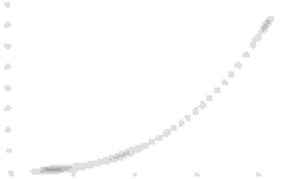
If I now compare my scaled MAF curve with the OEM curve (dividing my values by the OEM values), I get the folowing picture
The offset ist about 5% (maybe sclaling the primary injectors 5% up would have been the better thing to do here?) until the 2V range where it starts to rise until nearly 30%. It then starts to drop from the 2,6-2,7V point to reach the OEM values slowly. The high voltage cells are not measured as I do not see that much airflow. Highest voltage I saw at the MAF sensor was about 3,9V, in this area ther is still a good 10% uplift from OEM.
Does this look normal to you? The car has a RB Ram Air duct (connected to OEM airbox), exhaust header, cat and muffler exchanged. AEM coils, electric waterpump and the newer oil vent (where the hose from the oil inlet is connected to the combustion chambers) if that is any matter. The engine is not ported.
What seems funny to me is that I kept lifting up the MAF curve with every iteration but never saw a need to make a correction in the negative direction..
Your maf curve must look like a mad woman's lipstick!
I always try and use logic when tuning and to me it would be totally illogical to scale a maf curve like that .
This is not my MAV curve, but the curve that represents the percentage of difference to the OEM curve... The MAF curve itself looks about what it's supposed to look. It's just lifted up in General and esspecially in the middle w�re the mad womans lipstick peaks. I just plotted this curve as I wanted to visualise what I changed..
After logging I used a 3rd grade polynom to smoothen the curve in areas it didn't loo steady.
Probably I'll try again, starting of scaling down the primary injectors down by 6% as the lipstick curve suggests (the 2V area where the difference starts to rise could also be linked to the secondary injectors as this is about 4000rpm with low load), I'm interessted where this takes me.. This is mostly about learning stuff for me...
What is strange about my MAF curve form your experience?
To be hones I have no idea what shape the perfect MAF curve should have. I did not find any funktion that can be fitted through the OEM data without significant errors, I tried a 3rd grade polynom, exponetial growth and a parameterized power equation (suggested by user carbonRX8) neither of these works all the way trough the data...
Anyway, I think the "mad woman lipstick curve" (thanks for that name!) is a good way to visualize what has been changed to the MAF scaling so would still be interessted in similar plots of finished tunes anyone did. I would be interessing to see if these curves all look different or if there are any similarities (which would tell me that there are thinks that are usually "off" in the same direction with most setups...
Also with this curve I could see, that in the low power regime I was running about 5% lean without tuning and fuel trims, so I testet to scale the primary injectots down by 5% (with the OEM MAF scaling) today and this also brought down the fuel trims close to 0 in that area. I will follow this approach, let's see where it takes me.
The shape of the oem maf curve is actually made using sophisticated measuring equipment. With the stock air box you should only be making very minor changes to it. If you are having to make major changes you have a mechanical problem that needs rectifying. If you just make the changes and then fix the problem later .......... your tune will be way out with potential for engine damage if it ends up super lean.
If you have fitted a new intake ............ there is then a legitimate need to rescale the maf, but the actual shape of the curve should not deviate too much from the stock shape ..... just be a % higher or lower although often the idle section needs more scaling than areas above that.
I'm running the stock airbox connected to the RB RamAir duct. I wouldn't think that should change too mich as the section where the MAF sensor sits is still stock.
Actually the engine was running lean before the tune as the MAF underread to less fuel was added (partly compensated by LTFT). What could cause a problem like this? A vacuum leak should show more effect in the idle range, in my case deviations a biggest in the 2-3V range of the MAF, so just in the middle. Could this indicate a problem with the injectors?
Definitely could be that. But I would probably look at the easy things to test first ... like the maf sensor itself , the mesh screens , the o2 sensor , a vac leak (although you are correct ...idle would be affected the most).
The point being ............you are trying to tune out a fault , not fix it.
This is why I posted results.. If something is wrong, there is no sence in making it look good...
I will swap the MAF sensor for another used one to see if data looks different. Mesh screens are ok, i checked Thema (and replaced one oft Thema).
I will also fog-test the intake and exhaust to make sure there is no leak. If all of this is ok I could change the O2 sensor and if this doesn't do anything I'll have to take a look in the injectors.
The funnt thing is, I decreased the primary injectors by 5% and the CL range up to 2V looks really good by that. OL Im still more than 10% rich after this adjustment with the OEM MAF scaling...
So, I changed the MAF and O2 sensor for new parts (denso). I also tried to smoke test the intake which was not too successful, but I'm quite sure the intake is ok (having a small leak on the exhaust side manifold to catalyst though). Anyway, changing the parts changed everything, I'm pretty sure the MAF sensor was not ok before.
With the new sensor I saw a quite constant offest of 5% in the CL range up to 2,3V, so I scaled the primary injectors down by 5%. Fuel Trims look perfect with this, LTFT is still 0 after some 100km. I also made a test map setting the SSV to open at 5250rpm as I wanted to have a look on the secondary injectors, this is difficult with the normal setting as SSV and secondary injectors kick in at about the same time and it's impossible to say what is the cause of what in this case. I scaled down the secondary injectors by 2,5% and things look pretty good now with the OEM MAF scaling!
In the logs I can see there are 3 spotswhere the engine runs lean and 1 where it gets a little rich.
1. lean spot is when the SSV opens and the secondary injetors begin to work (about 4000rpm, 3V in this log)
2. lean spot is when primary 2 injectors begin to work (about 5200rpm, 3,3V in this log)
3. lean spot is when the APVs open (6250rpm, 3,6V)
4. rich spot is just after the VDI opens (7250rpm, 3,8V)
For the SSV you already told me the solution is to set a richer AFR target in the OL fuel table, as the switching for APV and VDI is also dependent on rpm and not MAF voltage I'm thinking this should also be the better solution here. For the injectors it's more difficult, there is no specific switching point, I's guess it's accually dependent on MAF voltage so I could adjust the MAF curve in the 3,3V range but probably setting the AFRs a little richer in the 5000-5500 rpm range will also do the trick...
Can you confirm these findings on lean/rich spots for our engine?
I'm pretty happy witch the car already, I see 4V on the MAF correponding to ~220g/sec on the OEM MAF scaling which should be not to bad for NA...
Does anyone have a MAF curve we can use with the AEM 3.5" intake, as a basis to start tuning off of? Could it possibly be posted here? On the mazdaspeed3 forums there is a sampling of those types of curves for various intakes (that affect the diameter of where the MAF sits) and it enabled them to have a good starting point to tune from: https://mazdaspeeds.org/index.php?th...intakes.10280/
 07-14-2022, 01:50 PM


 .... Still not logical that a maf 'curve' should look like that IMO.