Axial Flow Supercharger

 08-13-2005, 01:14 AM
#2226
Registered

A roots most certainly will spin without a belt. We did it on my friend's Grand Prix and that was with the bypass open. Ther's enough airflow. The bypass is more of a pressure relief valve than anything. There really isn't much flow through them.
 08-13-2005, 06:37 AM
#2227
hi
Join Date: May 2005
Location: MI
Posts: 70
Likes: 0
Received 0 Likes
on
0 Posts
Mine never spun without a belt and open 1 1/2" bypass. From my experience it needs a fair effort just to hand turn the pulley. I imagine it'll need more power to turn it from the roots side. Its not like spinning a turbine.
 08-15-2005, 06:39 PM
#2230

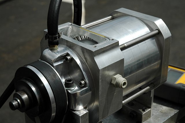
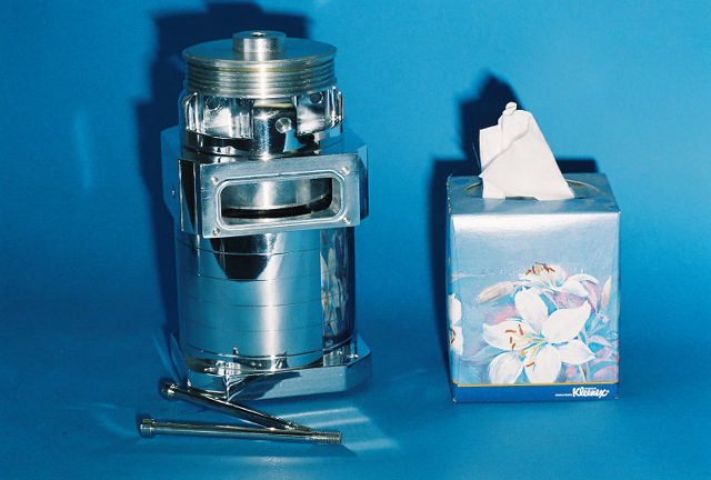
The outlet you see there has been modified for more flow then originally designed for. But to answer your question No, the shape is pretty much finalized. There will be a casting that directs the flow into a round tube. That then connects to a new intake manifold. These are first to be fab'ed for prototype then cast for production once the shape is developed.
As a side note, I intend to try and get the low end power up with longer primarys. This is doable since the top end is taken care of with supercharge. My final goal is to make the car more drivable everywhere. I can't promise it but I will put some time into trying with primary length. As long as I have to make a new casting it may as well do something.
As a side note, I intend to try and get the low end power up with longer primarys. This is doable since the top end is taken care of with supercharge. My final goal is to make the car more drivable everywhere. I can't promise it but I will put some time into trying with primary length. As long as I have to make a new casting it may as well do something.
08-15-2005, 06:49 PM
#2231
Registered
I do believe I mentioned a while back that I wanted longer primaries for low end too! Either we think alike or you are stealing my ideas!  j/k It's backwards thinking from everyone else and I like it.
Just get one installed on a car for visual appeal to be shown off at sevenstock. Already got the hotel.
j/k It's backwards thinking from everyone else and I like it.Just get one installed on a car for visual appeal to be shown off at sevenstock. Already got the hotel.
 08-15-2005, 07:01 PM
#2233
Administrator

thanks richard. 
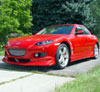
i wanna make a cardboard mockup and try fitment in my car give the wife something to go on about she thinks im a little obsessiverichard mayde you can send me a broken one?or a reject:D
you'd think the fella who took it could put something in the pic like a finger or a ruler for scale
i wanna make a cardboard mockup and try fitment in my car
give the wife something to go on about she thinks im a little obsessiverichard mayde you can send me a broken one?or a reject:Dyou'd think the fella who took it could put something in the pic like a finger or a ruler for scale
08-15-2005, 07:35 PM
#2236
Kaiten Kenbu Rokuren

Wow that thing is sexy! :D I really can't wait to see one installed. I guess I missed you posting a while back about making a new manifold, but that's good to hear. Keep up the good work Richard. You da man :p
 08-15-2005, 07:42 PM
#2238
Administrator
Originally Posted by rotarygod
I don't know if I'd ask him for a picture of a finger. You never know which one you'll get.
Originally Posted by Hymee
I thought some of the other shots had some things for relative size. Oh well. I didn't want to make it look like I was stealing every detail
Cheers,
Hymee.
Cheers,
Hymee.
i was just having some fun hymee. nice pics
i know i asked this before but just for clarification cause i cant find the posts- the TB will be bolted directlyto the inlet side ? or another way - the inlet of the blower will be bolted directly to the TB?
08-15-2005, 08:17 PM
#2239
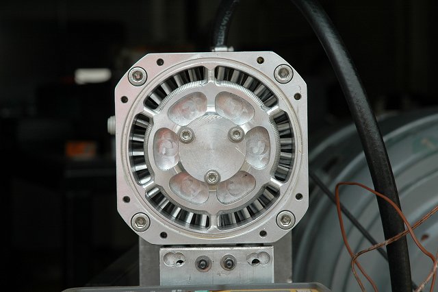
The TB will be ducted to the inlet. Right now the inlet is the rear of the compressor. Said inlet is now my avitar compliments of BaronVonBigmeat.
The outlet I think will be facing up as shown in the picture. There is plenty of room on top for the duct.
As I see it right now the unit sits close to the alt with all the room I can get next to the ABS. The ABS can be moved over about 3/4 of an inch if nessasary.
I haven't looked to see if the alt can be shoved over any.
The TB is going to wind up in front of the blower and the MAF might be where the airbox is. That will force the aircleaner behind the bumper. Maybe not, we shall see. The TB is a bulky thing.
BTW, Fred, did you see that blerb from someone about a throttle adjustment box available in Japan?
Zoom44, I'll PM you in a little while about some stuff.
08-15-2005, 09:10 PM
#2240
Administrator
Originally Posted by Richard Paul
The TB will be ducted to the inlet. Right now the inlet is the rear of the compressor. Said inlet is now my avitar compliments of BaronVonBigmeat.
i should have included this otehr pic by hymee earlier its a good one and matches your avatar
i was looking at everythin earlier and i agree the TB is a bulky thing. thanks for the insight Richard.
hey Fred!! you and I talked about longer primary runners at 7stock a YEAR ago:D

 !
08-15-2005, 10:09 PM
!
08-15-2005, 10:09 PM
#2242
Administrator
see i pointed that out and someone else said it was really an altenator just Mazda was using the name generator.
here https://www.rx8club.com/showthread.p...ight=generator
here https://www.rx8club.com/showthread.p...ight=generator
08-15-2005, 10:15 PM
#2243
Registered

Join Date: Mar 2005
Posts: 691
Likes: 0
Received 0 Likes
on
0 Posts
Mazda calls the Alternator on the Mazda6 a Generator too. Makes for one hell of an expensive part, whether it's just their nomenclature or an actual part differerence. I think, going off an old memory here, someone said the Generator in the Mazda6s was $600 from Mazda.
08-15-2005, 11:20 PM
#2244
Kaiten Kenbu Rokuren
What is the difference between an alternator and a generator? Do they create current/power in different ways? Or is it that the alternator is not independent like the generator? 
08-16-2005, 12:57 AM
#2245
Rotary only since 1980
Join Date: May 2003
Location: Southeast of Seattle
Posts: 587
Likes: 0
Received 0 Likes
on
0 Posts
Damn! That is one beautiful piece of precision machinery. Too bad it has to be hidden under the hood.
In looking at the inlet picture, I would have expected more inlet area. Maybe it is just the scale of the picture but it seems like a lot less area than the cross section of the current inlet tube. Is the sizing of the inlet area designed to accelerate the air flow?
I also wonder about managing the air flow hitting the inlet. Will you use some type of diverter, like the conical spinner on the front of a jet engine, to flow the air around the flat plate in the center? Just paint it black so it resembles the inlet spike on our beloved SR-71.
08-16-2005, 01:58 AM
#2246
Registered
Richard, why can't you do the inlet something like these with the tb on the front and have the outlet like the one you already have but at the rear instead? Wouldn't this take care of alot of packaging issues?
08-16-2005, 11:47 AM
#2247
Registered User

Join Date: Apr 2005
Posts: 89
Likes: 0
Received 0 Likes
on
0 Posts
Richard I think I found your fuel controller/ignition computer.
http://www.evasivemotorsports.com/me...ode=GReddy-ECU
"With the use of our "Optional Injector Harness" and the software, the unit has the ability to control an additional 16x16 injector duty cycle map and the controls for adding up to 2 additional sub-injectors. If the "Optional Ignition Harness" and the software are used the unit has the ability to control a 16x16 ignition timing map."
08-16-2005, 12:32 PM
#2249
Registered User
Join Date: Apr 2005
Posts: 89
Likes: 0
Received 0 Likes
on
0 Posts
Why wont he??
From the manuals it would appear to be very easy to program the MAPs
and they can be locked to prevent tampering if one was to use the EMS Ultimate.
Greddy even makes a pre-wired harness for the RX-8.
He could use it on the prototype designs to prove that this blower will work/what HP/TQ gains are to be expected until Richard designs his own controllers.