When you click on links to various merchants on this site and make a purchase, this can result in this site earning a commission. Affiliate programs and affiliations include, but are not limited to, the eBay Partner Network.
But isnt static pressure at outlet relatively close to atmosphere if you have an exhaust system that isn't too restrictive?
Yes, I've picked up that we cannot trust the absolute numbers from MAF, so that comparing what two different MAF's are giving is not sensible, but it might be that the same sensor would give us info regarding changes. For example, when you increase pressure to say 12psi, does your MAF reading go up by (14.7+12)/14.7 = 1.82 = 182%. I suspect that you see less, because filling is reduced from above 100%+ to something slightly less, for example 95%. Therefore (partly I guess), you need to have a bit more than 12psi to get a 182% increased reading from your MAF. This would might give us a picture about how filling/Ve changes during FI. Then we can use the numbers given by Mazda as reference for further estimations. Sounds sensible from your experience/numbers? ? It's just a loose theory in my head, caused by Teams input in his thread.
For a race pipe static pressure would be close to atmos. For anything with any bends or mufflers ...definately not.
And yes to above .I actually use the absolute load parameter as a guide to how much boost someone is running when I'm doing a remote tune ...it works out pretty accurate.
Sorry about the nagging, but because as I'm sure you've seen in Teams thread, the not too large difference between 13B-SI and 4 port Renesis made the difference between looking good and looking bad-ish, in the upper range of the chart. So the relatively small number changes does matter quite a lot apparently.
Just calculate how system behaves when FI compared no NA. In my head, calculated load would work, when NA you are peaking at around 105% load normally(mine RX8 anyway). Anything above 100% is obviously due to good intake design, maintaining an optimum air velocity and scavenge resonances. So I would be more than surprised if you was seeing 210% load at 14.7PSI. Anything above 200% would surprise me. My theory is that if you see for example 190% at 14.7PSI, then filling is down from 105%, to 95%, due to the scavenging effects we have at NA.
Gotya .
Something I have noticed is that the amount of power loss to drivetrain , as a % of the total , seems to be less as total power increases . So Ve per boost might not be a linear relationship but % power loss also drops and seems to more than make up for that .
So many variables ..............
Almost got me I thought about looking at VE vs pressure isolated, not mixing hp at all into the picture. Keeping everything else as identical as possible, same engine, same MAF, same stretch of road, same time of day and temp. Same shoes....:P
If we were to extract changes out from whp, then we are talking bloody Nobel price math.
Another variable ...
As boost pressure increases , the difference in pressure between whats at the fuel injector and what's inside the manifold decreases. The fact that I've never actually observed this phenomenon making any difference leads me to this conclusion:
The maf curve I use (which is a tweaked continuation of the stock maf curve) gets more optimistic as it climbs. Hence my earlier comment about wanting to change my tuning method . By lowering Ve as boost increases I can have more realistic maf numbers.
This wont make the Ve numbers accurate though, which is what you are interested in.
Anything above 100% is obviously due to good intake design, maintaining an optimum air velocity and scavenge resonances.
Just popping in to remind you and everyone else that it’s all due to the intake design and only the intake design. Specifically for the Renesis engine there are ZERO scavenging resonances due to there not being any overlap between when the intake port opens relative to when the exhaust port closed. It’s essentially a mild supercharging effect solely from helmholtz resonance of the intake system. Mazda clearly recognizes this which is why they aren’t wasting any time with anything more than the most basic exhaust manifold design. The next generation 16x engine exhaust manifold design too. They wouldn’t just leave that on the table except there’s nothing on the table to start with.
just couldn’t let that pass, so exit stage right ... Team out ...
I think my turbo was one of the first to be balanced on this new machine . Here is the video they sent me.X axis is rpm and y axis is out of balance . The green line is the max. out of balance spec. The first run is showing it unbalanced . Second run is after they took some material off the nut :
Some initial Results of 3582 hybrid turbo :
Spool up is almost the same as the 76mm wheel (100rpm slower)
Backpressure is down a little but not as much as hoped .
AAaf ... here is the same run , one logging boost (14psi)and AFR the next absolute load and the last a virtual dyno. It's interesting that earlier in rev range the load is lower and doest approach 200% till after the apvs open . All depends on maf scaling of course but the general trend that you were looking for is there :
Torque at 5000 feels very nice Max whp isn't spectacular , but ambient temps are up high ATM so that would account for a few horses.
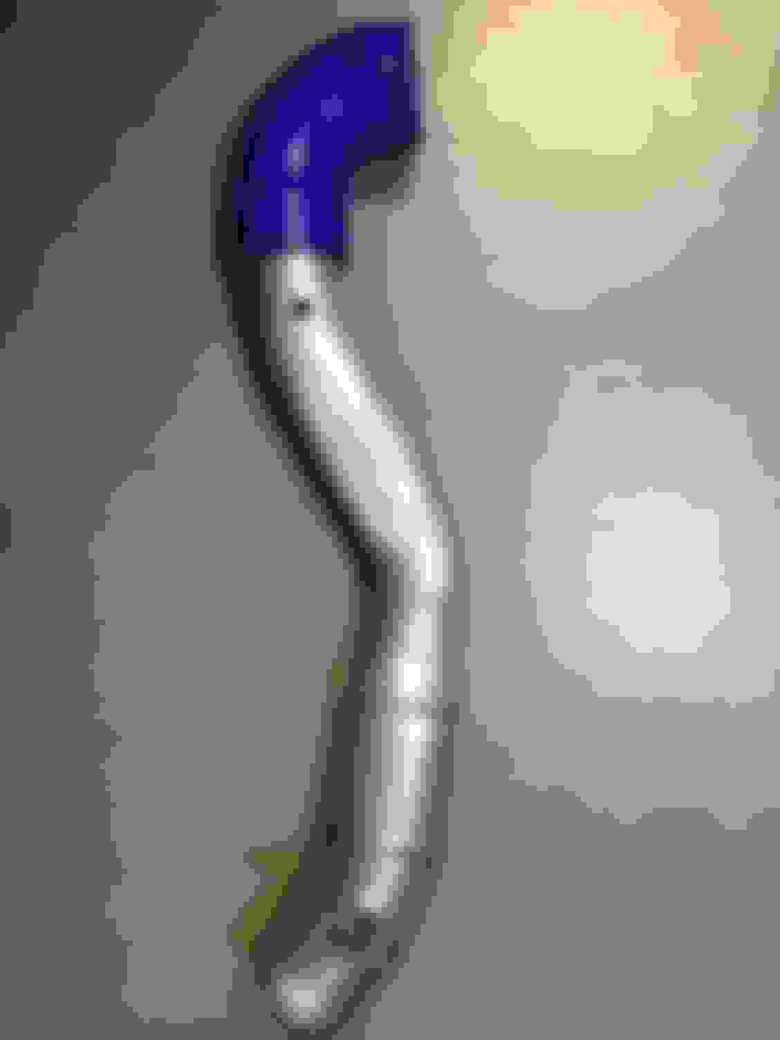
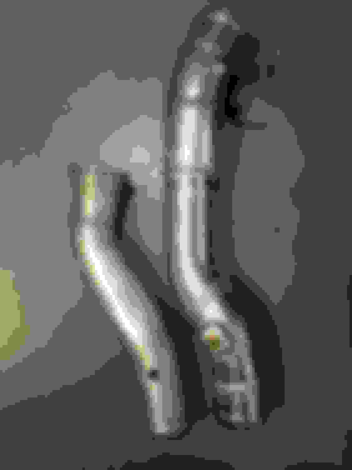
Am trying to replace the short piece of pipe off the turbo outlet . It was a 2" silicone elbow going to a 2" ali. pipe then expanding out to a 2.5" about a foot along from there .
This was done to get around the steering rod .According to an online calculator this short section is resonsible for over 2psi pressure drop at the flow levels I'm running.
I tried 2.5" but have given it up as impossible . Have ordered 2.25" tube to try and get that to work ...fingers xd.
Once this is done I'll book the dyno and see what she will do this time !
Being an RHD owner, I've found this pipe is one of the more challenging components to install. Hopefully you see some worthwhile gains. You may also get a few whp from replacing the tight radius elbows in/out of the IC with some longer radius bends.
The other area I think can be improved on the stock greddy is increasing the diameter of the piping between MAF sensor and compressor inlet. I know you've worked on this - are you at the final stage of development for this part of your setup? Could you give us a bit of detail on what you did here?
Being an RHD owner, I've found this pipe is one of the more challenging components to install. Hopefully you see some worthwhile gains. You may also get a few whp from replacing the tight radius elbows in/out of the IC with some longer radius bends.
?
Everything else apart from that one from the turbo is 21/2" or bigger .
Originally Posted by JimmyBlack
I know you've worked on this - are you at the final stage of development for this part of your setup? Could you give us a bit of detail on what you did here?
My turbo intake side is all 76mm now but the last part of it is flexible wire reinforced silicone tube. Not ideal ... but it seems to be hanging in there ok.
Really the pipe above is the only restrictive piece left .... really hope i can make 21/4" work .
I've done lots of improvements since my original 411whp dyno without being able to show any real peak power improvement . Instead of getting more power I was just getting the same power but at lower rpms . This trend is what lead me to my latest engine changes and with any luck ....the breakthrough I mentioned earlier.
It is def. a factor yes . As far as the VDI goes , I have that wired shut . The effect is gives on an NA car is nullified once you put boost into the engine .
 01-14-2018, 02:25 PM


 I thought about looking at VE vs pressure isolated, not mixing hp at all into the picture. Keeping everything else as identical as possible, same engine, same MAF, same stretch of road, same time of day and temp. Same shoes....:P