Harlan's Impossible turbo build.
 12-06-2014, 06:30 PM
#176

Got initial data to set up a MAP to MAF translator. Got the density vs IAT table written, now I need to figure out the math on getting a .5volt signal to correspond to 5.5g/sec. It's going to ramp up exponentially to 5 volts corresponding mass air flow at 30psi and 120degf. Then it will be all about getting a correct VE table. Pushing this idea forward right now, because if it works it will change a lot of the design of the build.
I think you should get away with figure 4-8, but you need to establish a regulated Vref from your relatively unstable 14.4V. Not difficult, for example this http://cds.linear.com/docs/en/datasheet/1965fb.pdf
If needed(most likely not) voltage references are available as well, they are even more accurate.

 12-06-2014, 07:05 PM
#178

Yeah the goal is to replace the MAF with a MAP and IAT. There is an off the shelf solution:
MAF Translator
But it seems simple and straightforward enough. Calc the volume from RPM and MAP then density correct with IAT and output a voltage that the ECU can read.
I have a second MAP sensor on order and I'm working on the code now. Should have something workable in a couple of days, and I'll just move my current MAP sensor downstream of the throttle.
In the meantime I can also work out any mechanical issues as they arise.
12-06-2014, 07:12 PM
#179

I still don'tt get why you want to replace something that can work perectly well ............ . Maf can be problematic , but with good design it works superbly .
What you are doing looks like makeing it complicated just for the sake of it .
What you are doing looks like makeing it complicated just for the sake of it .
Last edited by Brettus; 12-06-2014 at 07:29 PM.
12-06-2014, 08:23 PM
#180
While I'm not above complicated just for the sake of it, the MAF must be mounted in the bumper to be far enough away from the water injection so the hot wire doesn't get wet. I'm kinda amazed it works at all, it was one of my concerns before I got the turbo/WI installed.
The MAF I'm using barely fits and has a voltage bridge (resistor mod) to get the range I need and I don't like it.The sock maf wouldn't be any better in a housing that fits in the bumper, so I'm stuck finding a MAF that will fit where I need it and has enough range or carving up structure in the front and put in what I want. Lets try this first if it doesn't work then I'll have less distance to backtrack when I go another direction. If it does work maybe I'll release a kit.
Just checked running dual PWM to increase the precision. It works just like the writups and at 30khz there is no noticeable ripple with the cap and resistors I've set up. I'm down to 0.01 volt increments from 0-5volts. I've also calculated how much to add to the signal from the MAP to reference it at zero absolute pressure. This way when the value for pressure doubles the mass air flow doubles. Should be able to get it refreshing 100 times per second since the math boils down to a couple multiplications and then a bitshift instead of division. It will probably fit in the boost/WI controller code without slowing things down much, and most of the inputs would be shared anyway. If it doesn't work I should know soon enough.
12-06-2014, 09:08 PM
#182
Above the cross-member with filter? I'm not doubting it's possible, but I wedged everything up there but am not happy with the results. Right now my MAF is pinched between the hood release and bumper. Can't move it to the right because the elbow is in the way, cant move it left because that's where the filter goes. I could go with another MAF or the stock MAF with another housing and if this doesn't work that's the direction I'm probably going.
Guess I could add another elbow on the left and drop the filter below the cross-member, but that becomes a mess, and requires a splash guard otherwise things will get dicey in the rain.
At this point electronics are my strong point and fabrication is my weakness. If I can take the whole intake and trade it for an elbow and a filter that work well and look good I'm going for it.
12-06-2014, 09:20 PM
#183

I feel the same way. I so want to be done with my build, but I don't want to go back and forth doing crap over and over. So I'm aiming for everything I could ever need. A lot of it is excessive, but just trying to cover all the basses.
Keep up with it man, don't get over anxious and blow your engine.
Keep up with it man, don't get over anxious and blow your engine.
Love the initiative from both you and Harlan, homebrew is awesome!
12-06-2014, 11:48 PM
#184
SARX Legend
iTrader: (46)

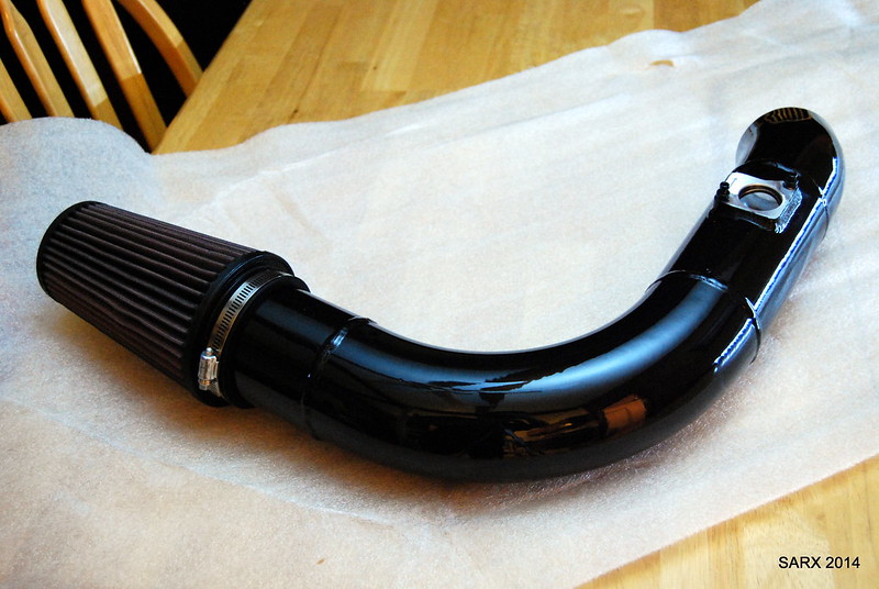
Harlan, this is my intake, it is for the Greddy kit but could be made to work with yours without a ton of fab. It has a honeycomb air straighter before the MAF and both it and the MAF flange can be placed anywhere in the pipe that I want. The piping is 3.5" and the ID of the MAF section matches the stock MAF tube. So far we know it fits with plenty of room under the stock bumper and the Mazdaspeed. Sifu had an earlier version (more sections of pipe and couplers) on his that did have to be modified for his Vertex front bumper but it was no biggie.
Last edited by 9krpmrx8; 12-08-2014 at 11:01 AM.
12-07-2014, 07:01 PM
#185
Damn 9k that's a nice looking intake! Wish my fabrication skills were beyond throwing pipe, couplings and duct tape together until it doesn't leak.
MAF MAP converter is written. Right now it should be at around .5v at idle, and go up to around 5v at 30psig, 10000rpm and 100degf assuming VE of 100%. So it should idle and not run out on the top end.
The VE table will take some tweaking, but the code runs about 1000 times per second by itself. It will run a bit slower when loaded down with the boost/WI controller code but the car should run fine.
Working on the knock controller as well. Need to do some more bench tests to figure out what's going on. Regardless of the problem it's what's holding back WOT runs. I'll get some recordings from my det phones so you guys can hear what I hear.
I may be going back to an earlier and simpler version of the knock detection. If so I could have all my control functions on one microcontroller. It would be less precise at detecting knock but if it's a trade-off for reliability it might be worth it.
Should know what works and what doesn't tomorrow.
12-10-2014, 12:55 PM
#186
Idled and revved it in the driveway with the MAP to MAF converter. Still working the bugs out, but I did have it purring at idle for one attempt. Currently the bug list is:
Water in the MAP sensing line throwing readings off.
Initial flow to tell the ECU while cranking.
ECU draws a surprisingly large amount of current from the MAF.Surprisingly small resistors I used for feeding the ECU.
So it may be a while before this goes on for good, but it does show promise.
Water in the MAP sensing line throwing readings off.
Initial flow to tell the ECU while cranking.
ECU draws a surprisingly large amount of current from the MAF.Surprisingly small resistors I used for feeding the ECU.
So it may be a while before this goes on for good, but it does show promise.
Last edited by Harlan; 12-10-2014 at 01:07 PM.
12-26-2014, 08:56 PM
#188
Threw out the MAP to MAF converter. Not saying its impossible or that I'm giving up completely, just a bit more then I'm willing to chew on right now. Oddly the hardest part was getting a clean RPM signal from the ignition coil 5v.
Right now I'm getting the parts together to rework the intake in aluminum with a stock maf in a 3.5 housing and flow straightener. I'm also getting the parts to do a straight shot from the turbo to the throttle body instead of the ugly flex hose.
Just reworked my electronics to tuck everything into the glove box as a stepping stone to a permanent system in the dash. When I'm done the install should be so clean that nobody will know I'm non stock without opening the hood.
Oh and in other news the 3" Agency Power Exhaust with a auger insert sounds great with the turbo. No drone, doesn't sound ricey, and is just a bit more throaty than stock.
Here is my display unit in case anyone is curious. Eventually I'm going to put the LCD in the moon panel under the radio and tuck all the electronics in the hole back there.
01-04-2015, 05:39 PM
#189
Got a bit done today. Test fit the LCD in the moon panel. Started redoing my intake and charge pipes, so here is a preview of the MK2 intake it's mostly parts from the PTP intake cut up and reused. Also here is a picture of an attempt to use clear resin to make a window in the moon panel. It ended up a bit too bubbly/hazy so I didn't use it, but the surface was very smooth.
Last edited by Harlan; 01-04-2015 at 05:48 PM.
01-05-2015, 12:23 AM
#190
Curious, is there a specific reason you are using the PTP intake? I completely replaced it all the way from filter to compressor inlet for about $150. That included a filter, MAF housing with honeycomb, 90 degree aluminum elbow, section for BOV recirc and vac lines, silicone elbow to compressor and couplers. This way the entire intake is stock diameter for the MAF until the compressor where the silicone elbow increases to 4" to match the compressor inlet.
Last edited by slash128; 01-05-2015 at 12:40 AM.
01-05-2015, 12:45 AM
#191
MAF under bumper, not smashed. About the only issue I've had is potential for the MAF connector getting wet during heavy rain or wash, but i just threw a ziplock bag over it 
01-05-2015, 09:03 AM
#193
I used the PTP turbo intake because I had it on hand and could toss it on during my time off work. More parts are on order, it's going to eventually be 3.5" to the turbo intake with an aluminum elbow and aluminum injector bung preturbo.
01-06-2015, 04:59 PM
#195
Mini update while waiting for parts. I have the moon panel wired with display and a rotary encoder as a **** and an RBG led. Looks crappy for now, but functional. Still working on the knock lockout, trying a different approach to get less false positives.
But more importantly than all that my display is now set up to send all the controllers info as comma separated values every 10th of a second via usb serial. So I can log IAT vs MAP as well as knock and water injection. I really should have done this earlier!
Through all testing so far I haven't seen more than about 120F in boost. Granted that will come up with pressure, but the pre-turbo injection really hits the spot so far.
Also dealing with some rust/plugging of the water injector. Next bung will be aluminum and not steel.... Didn't think it would become an issue this quick though.
Also I may have solved the RPM reading problem... so if it works it will simplify a lot of things.
Last edited by Harlan; 01-07-2015 at 09:25 PM.
01-07-2015, 09:56 PM
#196
Also I put a TI TPIC8101 knock processor on order. If I can interface it I'm throwing out all my knock sensing code that took so long to write. Funny thing is a couple years ago I saw that they were available but I had no clue how to work with them so I went writing my own because it was easier. Now I've played with enough similar stuff that it shouldn't be that bad to set up software to interface via SPI.
Everything is moving to one board that will control all functions. May even tie in a boost a pump to it all at this rate.
Everything is moving to one board that will control all functions. May even tie in a boost a pump to it all at this rate.
01-08-2015, 10:47 PM
#197
Working on UI and display while waiting for electronics parts to arrive. Here is a pic of testing the display in place. With the LCD off it looks not unlike a stock panel with a ****. Need to clean up the surface and reapply the tint, but this gives me an idea of what it will look like when it's done. Eventually I might use optical touch sensors and make it look completely stock, but that's too much work right now.
01-08-2015, 11:53 PM
#199
The **** is so I can view different parameters, reset peak values, and change my boost profile.
I'm setting up right now to have peak boost, IAT, knock, and WI flow as well as ways to reset the peak value. It also needs to have a way to program different psi through the rev range or at least to change profiles. I don't mind hooking up the laptop to create a new profile, but having several to choose from is key.
Also it should switch to the important parameter at any give time automatically. If pressure gets >2psi for example it should show boost in bar form with numbers and peak, then if knock begins to happen it should show knock and WI rate.
Oh and it also has a RGB LED for an indicator to draw attention to the display if something bad is happening.
Right now it's just window dressing, the meat of the code works very well with the exception of knock sense/lockout and I'm working on that.
Unfortunately it's all I can do until the rest of the parts come in.
