Pettit Super Charger Owners
 04-28-2009, 06:31 PM
#5126
Registered

Join Date: Jan 2006
Location: Maryland
Posts: 1,257
Likes: 0
Received 0 Likes
on
0 Posts
Thats why I recomend engine ice.
http://www.engineice.cc/
Spend the extra few bucks, it make it well worth the corrosion inhibeters that it contains.
http://www.engineice.cc/
Spend the extra few bucks, it make it well worth the corrosion inhibeters that it contains.
 04-28-2009, 07:16 PM
#5127

on a non pressurized system water wetter will foam like a drunk epileptic. Use DEI --no foaming and it turn the water a pretty purple.
Rotary's without heat spots? I would love to have one of those. SMILE
stand corrected on the lack of boost theory--thx Moon.
It will be interesting--wish we had vavlves then this ? would be easy to answer. Its the low rpm low speed thing that gets me.
OD
Rotary's without heat spots? I would love to have one of those. SMILE
stand corrected on the lack of boost theory--thx Moon.
It will be interesting--wish we had vavlves then this ? would be easy to answer. Its the low rpm low speed thing that gets me.
OD
04-28-2009, 07:49 PM
#5128
Registered
Join Date: Jan 2006
Location: Maryland
Posts: 1,257
Likes: 0
Received 0 Likes
on
0 Posts
Just imagine when you pull an engine appart and look in the water jacket, usaully you find some corroded spots. Ive pulled 2 engines appart that have run the stuff and you never see anything but a brand new looking water jacket, the gaskets look new also and thats on the jetski motor wich was run in salt water most of its life, what killed that motor was getting stuck in sand and continuing to run it to get it off the sand bar. The motor had around 70 hours (2 seasons) on it. If you ever get a chance stick your finger in some and you will find it very slick, that id say is a seal saver also. Man youd think im a salesman for the company but im not. I just reccomend it. I run it in everything I own from jetski to quad, I ran it in my 8 and plan on changing my 09 over to it when I get the time and add the coolers.
 04-28-2009, 11:13 PM
#5130

on a non pressurized system water wetter will foam like a drunk epileptic. Use DEI --no foaming and it turn the water a pretty purple.
Rotary's without heat spots? I would love to have one of those. SMILE
stand corrected on the lack of boost theory--thx Moon.
It will be interesting--wish we had vavlves then this ? would be easy to answer. Its the low rpm low speed thing that gets me.
OD
Rotary's without heat spots? I would love to have one of those. SMILE
stand corrected on the lack of boost theory--thx Moon.
It will be interesting--wish we had vavlves then this ? would be easy to answer. Its the low rpm low speed thing that gets me.
OD
Everything I read on WaterWetter just leads me to believe it's evil stuff. I think I'll post that post as a thread somewhere just so everyone else is aware.
Now, this Engine Ice stuff, I've never heard of that. I saw it in FF4 but I thought it was some fictional brand. How's it work?
Oh! And we got a little side tracked on the Engine diagnosis, didn't we? Any more ideas?
04-29-2009, 12:39 AM
#5131
Registered

Join Date: Apr 2006
Location: Mesa, Arizona
Posts: 84
Likes: 0
Received 0 Likes
on
0 Posts
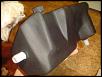
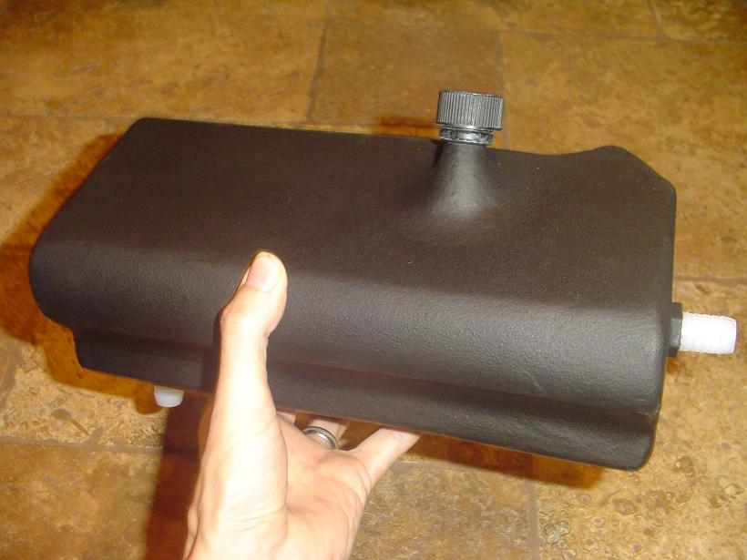
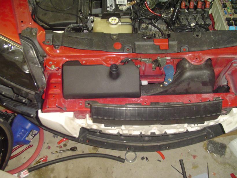
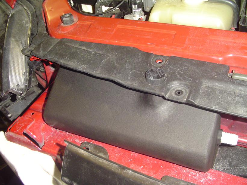
I got an itch to build something out of fiberglass recently and built a IC reservoir that goes inside the front bumper. Was getting frustrated with pump lossage of prime so wanted pump mounted lower. Other nice side effects is increased space, reservoir out of hot engine bay, larger capacity, and partially plugging up the recirculation swirl oldragger says might develop with the RB Revi Ram air duct.

 04-29-2009, 04:05 AM
#5134
Londons Yellow Peril

looks very cool (hoho). How do you tell if its full or not tho!
At least our current one you can see the coolant levels and wether the pump is running or not, from the coolant churn....
At least our current one you can see the coolant levels and wether the pump is running or not, from the coolant churn....
04-29-2009, 07:25 AM
#5136
Rotary engine addict

Join Date: Jun 2008
Location: Guadeloupe (FWI)
Posts: 303
Likes: 0
Received 0 Likes
on
0 Posts
OK, some picts.
but I am kind of lost with the pdf file, I think their is two version of the kit...
let me explain :
On the page 28, it is said to cut the air temp sensor wires and to connect them to the new manifold air temp sensor�what sensor ?
I looked for it a long long time and I think it is not for my kit as my air filter connector is not the same then on the pdf file � mine has a place to plug the normal sensor�
can you please confirm that I do not have to cut anything ??
by the way, what should I do with the purge control vavle ?? I did not see where it is plugged next ?
thank you
04-29-2009, 07:49 AM
#5137
Joff, your tank looks nice. I considered making my own but decided not to (too lazy). I like your idea of a new location.
Last edited by Phil's 8; 04-29-2009 at 08:44 PM.
04-29-2009, 10:38 AM
#5138
Registered
Join Date: Apr 2006
Location: Mesa, Arizona
Posts: 84
Likes: 0
Received 0 Likes
on
0 Posts
If I had to do it again, I wouldn't have built it out of fiberglass. A much simpler reservoir would have been to take some 3" PVC tubing, cap them, put some barb fittings in and mount it across the bumper bar. That'd give plenty of volume too. There's really no need to do what I did by molding the reservoir to the profile of the area, but I kind of wanted to an excuse to experiment with fiberglass.
04-29-2009, 10:43 AM
#5139
whines all the way home
iTrader: (2)

Join Date: Oct 2004
Location: Towson/Baltimore, MD
Posts: 7,402
Likes: 0
Received 2 Likes
on
2 Posts
Thats a great idea,, that will be my next cooling mod,, I did take delvery of Cams new secondary rads Friday, I just didnt want to post pics til all theories with Zens car had been exhausted, Ill post them tonite...
04-29-2009, 12:19 PM
#5140
Registered
Join Date: Jan 2006
Location: Maryland
Posts: 1,257
Likes: 0
Received 0 Likes
on
0 Posts
OK, some picts.
but I am kind of lost with the pdf file, I think their is two version of the kit...
let me explain :
On the page 28, it is said to cut the air temp sensor wires and to connect them to the new manifold air temp sensor�what sensor ?
I looked for it a long long time and I think it is not for my kit as my air filter connector is not the same then on the pdf file � mine has a place to plug the normal sensor�
can you please confirm that I do not have to cut anything ??
by the way, what should I do with the purge control vavle ?? I did not see where it is plugged next ?
thank you
but I am kind of lost with the pdf file, I think their is two version of the kit...
let me explain :
On the page 28, it is said to cut the air temp sensor wires and to connect them to the new manifold air temp sensor�what sensor ?
I looked for it a long long time and I think it is not for my kit as my air filter connector is not the same then on the pdf file � mine has a place to plug the normal sensor�
can you please confirm that I do not have to cut anything ??
by the way, what should I do with the purge control vavle ?? I did not see where it is plugged next ?
thank you
04-29-2009, 05:47 PM
#5142
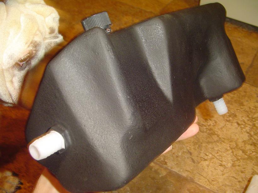
that is a cool tank man--really nice work. Really nice. talented guy that likes to tinker!
Now what keeps the tank from loosing prime is that the return fitting area INSIDE the tank must be submerged. Otherwise at some point you can loose prime. Just run a tube in there so the return flow is submerged. Phil the Moroso tank has that. The Moroso tank holds more that 3.5 qts. How about almost 6 qts!! No kidding. It does keep temps down a little longer. it also has bigger hose fittings.
OD
 04-29-2009, 07:28 PM
#5145
whines all the way home
iTrader: (2)
Join Date: Oct 2004
Location: Towson/Baltimore, MD
Posts: 7,402
Likes: 0
Received 2 Likes
on
2 Posts
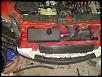
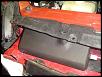
And while we're on the subject of cooling,,,
here are pics of the secondary rads that Cam will be making an initial batch of ten and further more upon interests,,,,
Cam has been running this setup on his car for the last 8 months or so and is satisfied to the point to bring it to the public,,,


here are pics of the secondary rads that Cam will be making an initial batch of ten and further more upon interests,,,,
Cam has been running this setup on his car for the last 8 months or so and is satisfied to the point to bring it to the public,,,
04-30-2009, 06:30 AM
#5148
Yup, available thru BHR or from Summit Racing. I got mine from BHR he was a little less expensive than Summit. Since my radiator overflow reservoir is also deteriorating I ordered one of those from Moroso (thru BHR).
Last edited by Phil's 8; 04-30-2009 at 12:40 PM.
04-30-2009, 09:36 AM
#5149
Rotary engine addict
Join Date: Jun 2008
Location: Guadeloupe (FWI)
Posts: 303
Likes: 0
Received 0 Likes
on
0 Posts
That should have been removed since the Flash, ignor the cutting of the wirers from the MAF sensor plug. As for the purge control valve it should hook to the bottom back 1/4 hose of the blower (intake side). Run the other output of the purge valve to the what seems like the fuel return but vents the gas tank. Its not critical wich hose goes were on the purge control valve.

now for the purge control valve, not sure yet I have found every thing...
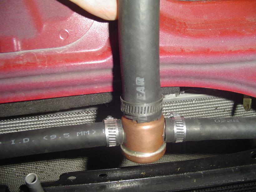
Can you please look at the following picts and help me finishing my installation.
the pict 01 et 04 are to confirm if it is good or not.
the others are interogation I have about those parts

after that I think I am done !!!
 04-30-2009, 10:45 AM
#5150
ok --of the top of my head---your brake booster line is correct--pic #1
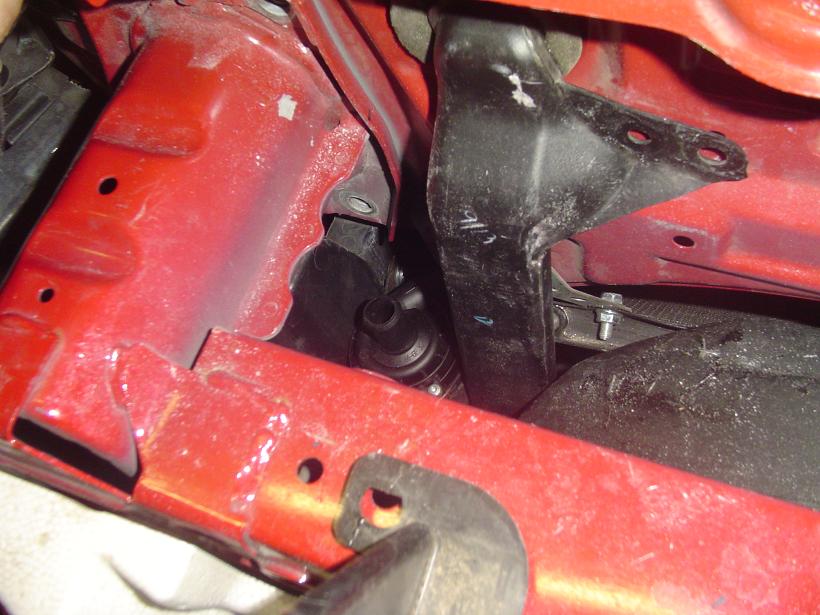
pic # 2 is the purge? I cant remember about that one
pic 3 the by pass valve has to have a good vacuum source WITHOUT a check valve in the line. Vacuum source also needs to be after the s.c.
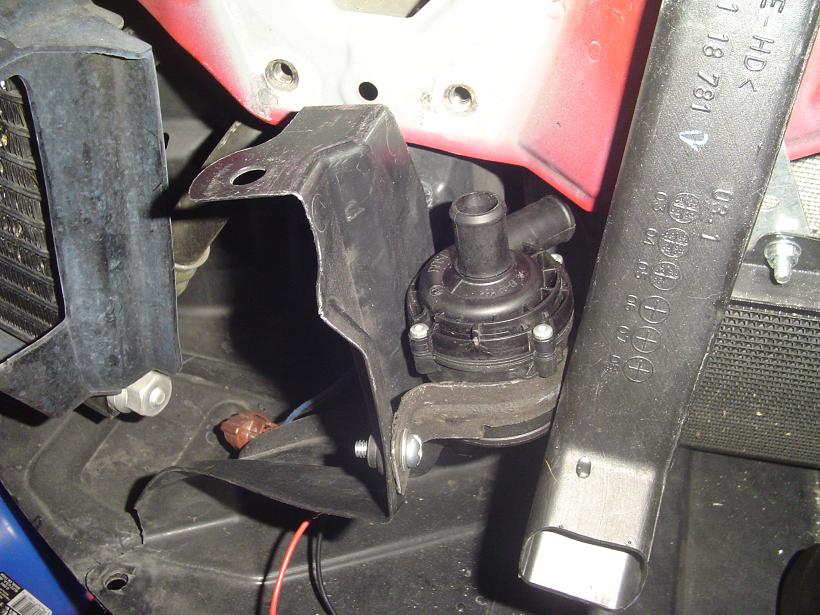
pic # 4 the vacuum source off the upper intake manifold is the one I used to supply the vacuum tank --one with all the solonoids on it. I think--i either did that or that was the one I used to supply the by pass valve--will have to look tonight after work--damn old brain.
pic # 5 yep both those pointer spots need vacuum!
Wheres the square shaped vacuum tank you cut off the oem manifold?
Almost done --!!!!
Careful on the 1st crank--turning on all the elctricals at once after they have been down a while can blow a fuse.
OD
pic # 2 is the purge? I cant remember about that one
pic 3 the by pass valve has to have a good vacuum source WITHOUT a check valve in the line. Vacuum source also needs to be after the s.c.
pic # 4 the vacuum source off the upper intake manifold is the one I used to supply the vacuum tank --one with all the solonoids on it. I think--i either did that or that was the one I used to supply the by pass valve--will have to look tonight after work--damn old brain.
pic # 5 yep both those pointer spots need vacuum!
Wheres the square shaped vacuum tank you cut off the oem manifold?
Almost done --!!!!
Careful on the 1st crank--turning on all the elctricals at once after they have been down a while can blow a fuse.
OD