Electrical Gauge(s) - Grounding Sending Units
#1
Electrical Gauge(s) - Grounding Sending Units
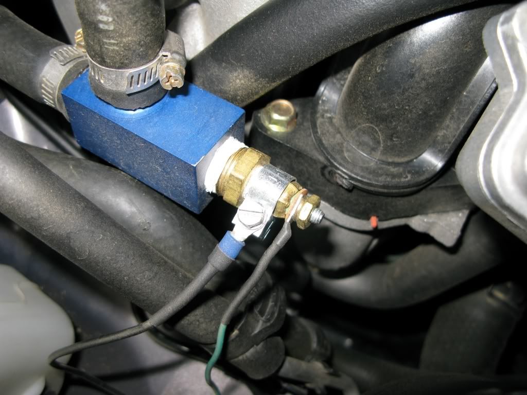
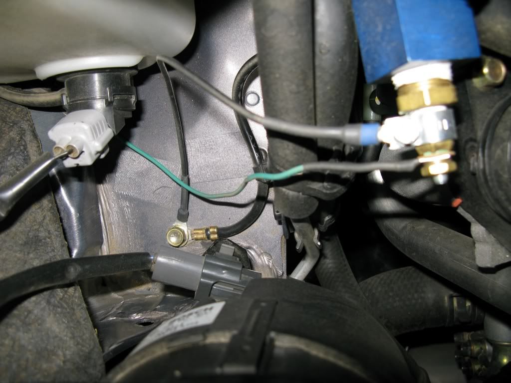
Here's some pics of some grounding locations that you can use for the sending units for electrical gauges (e.g., oil & water temp, oil pressure). Teflon tape was used to seal the units to the Racing Beat sensor adaptors so small hose clamps were used to attach the grounding wires to the sensors, as can be seen in the pictures.
Please excuse the dirty engine bay ... didn't get a chance to clean it before the pics were taken.
Requirements:
* Exacto knife
* Being a contortionist and double-jointed helps a lot working underneath the dash and steering wheel
Water temp sending unit:
Body of sending unit grounded with hose clamp and wire to the chassis
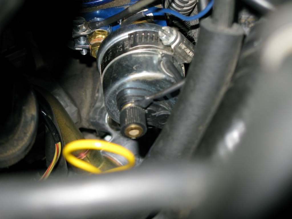
Oil pressure and temperature sending unit:
Body of the oil pressure sending unit grounded with a larger hose clamp and wire; body of the oil temperature sending unit can be seen above (behind) and to the right of the large oil pressure sending unit. It was grounded the same way as the water temp sending unit. Just a side note: it's best to connect and tighten ALL the sending units and wires to the RB oil adapter before you install the adapter --- you won't have very much room to turn wrenches down there once it's installed.
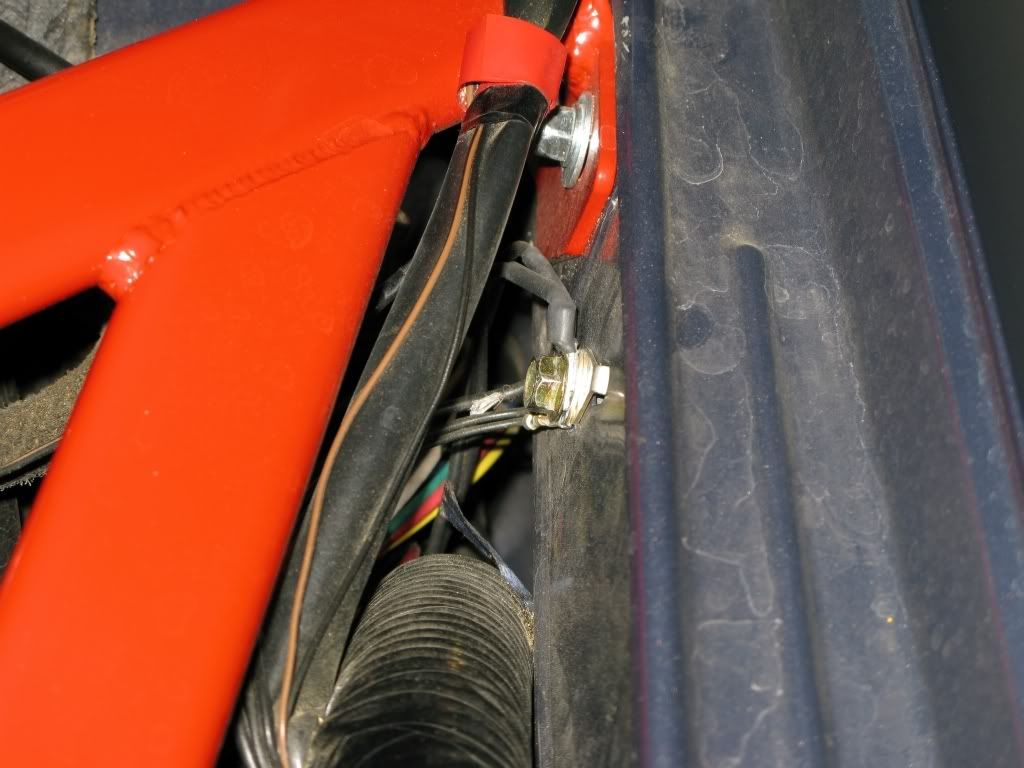
Both the grounding wires of the oil pressure and temp sending units were attached here (near the brake master cylinder and hood hinge area)
Routing wires from the cabin to the engine bay:
Access to the engine bay can be made through the large rubber grommet just above and to the right of the clutch pedal. This grommet already supplies a large bundle of wires to the engine bay, but by cutting a slit in the grommet, in the trough surrounding the existing wire bundle, you can push your wires through to the engine bay. They'll exit just below the master brake cylinder.
Rubber grommet is just behind the brake pedal in this picture
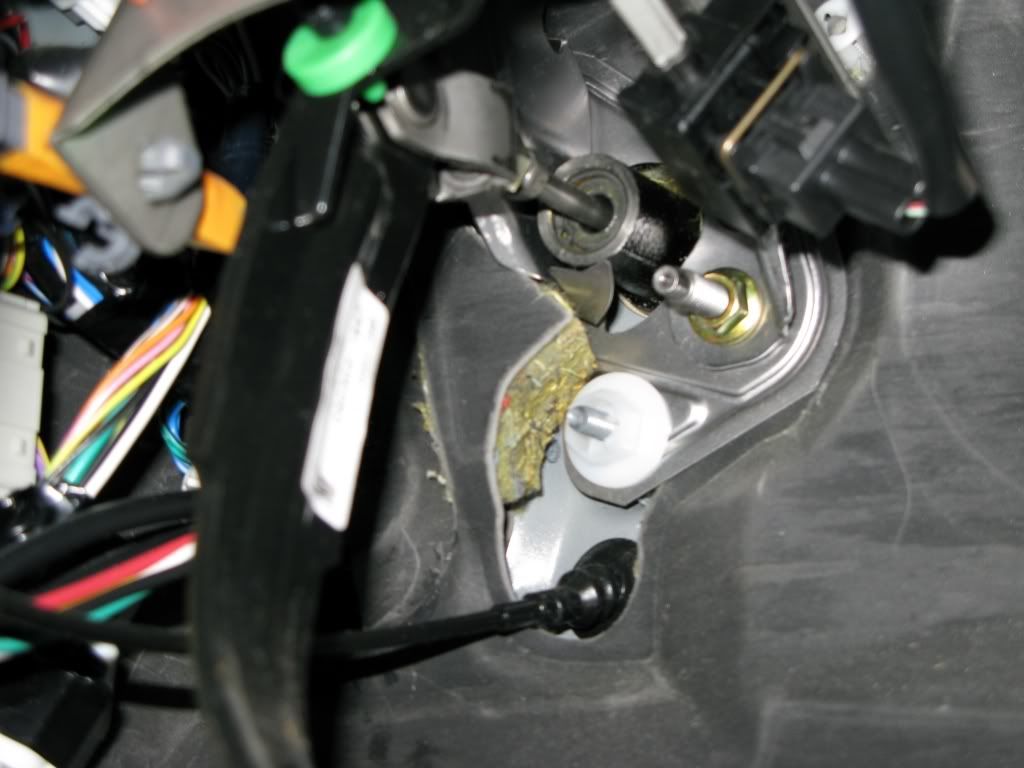
Close-up of the grommet. Note that there's kind of a rubber flap that straddles and covers the large wire bundle --- this can be lifted up and out of the way for better access to the grommet. You can see the wires (six 18-gauge wires and two larger black wires for the Tein EDFC) that I fed through just inside the rubber-like flap that covers the grommet. I used the Exacto knife to cut a 0.5 inch (approx.) slit in the trough for the wires. I tried resealing that section with silicone sealant, but it got a little messy (and probably not necessary anyway).
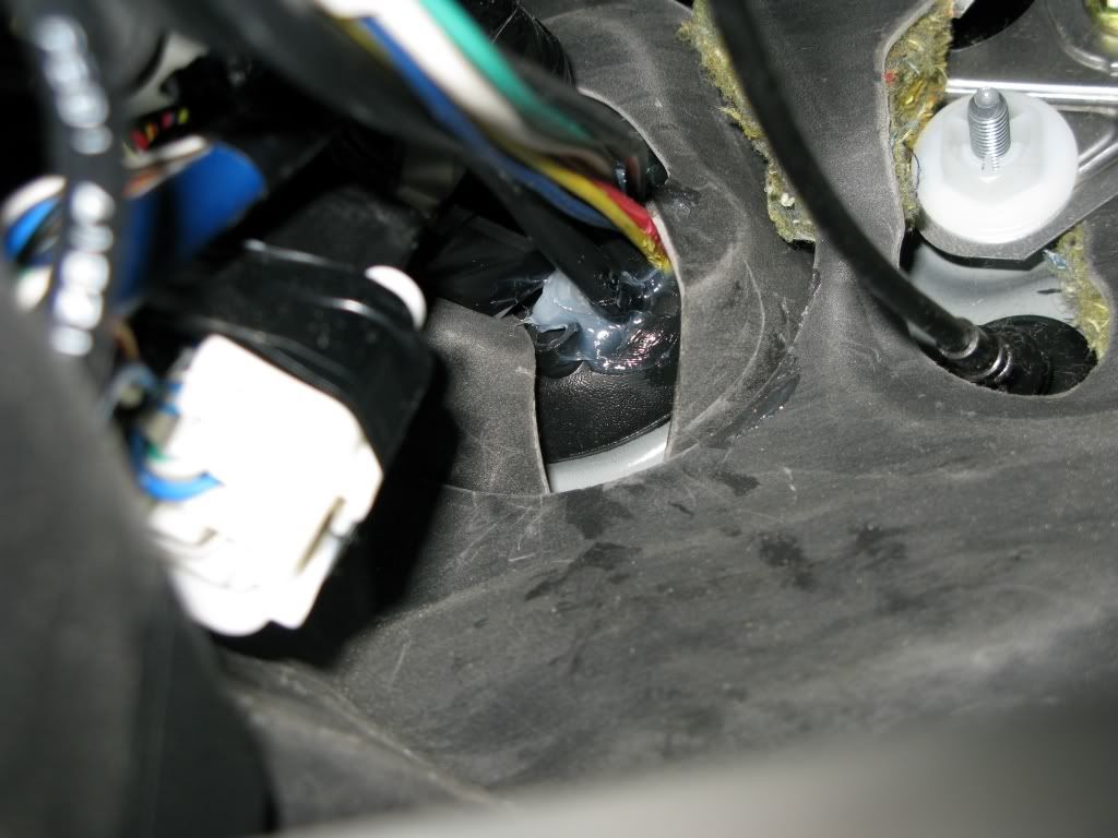
Please excuse the dirty engine bay ... didn't get a chance to clean it before the pics were taken.
Requirements:
* Exacto knife
* Being a contortionist and double-jointed helps a lot working underneath the dash and steering wheel
Water temp sending unit:
Body of sending unit grounded with hose clamp and wire to the chassis


Oil pressure and temperature sending unit:
Body of the oil pressure sending unit grounded with a larger hose clamp and wire; body of the oil temperature sending unit can be seen above (behind) and to the right of the large oil pressure sending unit. It was grounded the same way as the water temp sending unit. Just a side note: it's best to connect and tighten ALL the sending units and wires to the RB oil adapter before you install the adapter --- you won't have very much room to turn wrenches down there once it's installed.

Both the grounding wires of the oil pressure and temp sending units were attached here (near the brake master cylinder and hood hinge area)

Routing wires from the cabin to the engine bay:
Access to the engine bay can be made through the large rubber grommet just above and to the right of the clutch pedal. This grommet already supplies a large bundle of wires to the engine bay, but by cutting a slit in the grommet, in the trough surrounding the existing wire bundle, you can push your wires through to the engine bay. They'll exit just below the master brake cylinder.
Rubber grommet is just behind the brake pedal in this picture

Close-up of the grommet. Note that there's kind of a rubber flap that straddles and covers the large wire bundle --- this can be lifted up and out of the way for better access to the grommet. You can see the wires (six 18-gauge wires and two larger black wires for the Tein EDFC) that I fed through just inside the rubber-like flap that covers the grommet. I used the Exacto knife to cut a 0.5 inch (approx.) slit in the trough for the wires. I tried resealing that section with silicone sealant, but it got a little messy (and probably not necessary anyway).

Last edited by elf; 10-09-2007 at 05:54 AM.
#2
awesome thread Elf!
Did you click on the image button and past the 'direct link' from your photobucket account?
that definitely looks like a good place to run the wires from the bay to the cabin. I guess there really is no reason to go down into the transmission with Electrical guagues. Nicely done!
Did you click on the image button and past the 'direct link' from your photobucket account?
that definitely looks like a good place to run the wires from the bay to the cabin. I guess there really is no reason to go down into the transmission with Electrical guagues. Nicely done!
#5
Thanx Razz and Jedi ....
Linked pics don't seem to display in the DIY section like in the other forums on this site ... and I like somewhat large pics, so I don't normally use the Attach Files for pics ... oh well.
Linked pics don't seem to display in the DIY section like in the other forums on this site
 ... and I like somewhat large pics, so I don't normally use the Attach Files for pics ... oh well.
#7
Thread
Thread Starter
Forum
Replies
Last Post
ShellDude
RX-8 Parts For Sale/Wanted
5
10-01-2015 09:55 PM
jasonrxeight
RX-8's For Sale/Wanted
2
09-30-2015 01:53 PM
Learners_Permit
Series I Interior, Audio, and Electronics
8
09-27-2015 07:38 PM


