Fuel pump circuit logic
#1
Fuel pump circuit logic
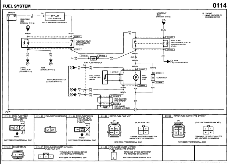
I've been studying the wiring diagram relative to the fuel pump subsystem and have collected info from various posts. If I have now understood correctly the circuit can be described as follows:
1. they designed the system to provide differing levels of pressurization - low vs high - which is simply the single pump operating at differing speed/capacity
2. the difference is merely at two specific levels and is determined by a resistor in the circuit.
3. there are two distinct relays in the system - one designated low pressure and the other high pressure. In reality the relays are in series with the first one being that for low pressure. When this one engages the resistor is in the circuit to the pump. When the 2nd relay, the one for high pressure, is activated it merely shorts and in essence removes the resistor from the circuit.
4. the 1st relay, low pressure, has it's solenoid connected on the + side to the power coming off the main engine relay (ignition on) while the - side is to the PCM circuit. I assume that if the immobilizer hasn't recognized the key, this circuit will not complete for the fuel pump. The diagnostic connector bypasses this entirely.
Have I missed something?
#3
As said, I did pull all the posts/threads I could find. I pieced together and relevant cross references. I am certainly repeating what I found in the various threads so the question is to understand if there are other specific points/info that I didn't find. I mean there are other information relative to connectors, wires, location, etc, that I found/have but my focus is on the logic. To make it complete I probably should figure what the PCM adds, but I think that's more specific to how the 2nd relay gets activated.
#4
There’s no secret sauce here.
When you turn the car on it starts up by running the fuel pump power through a resistor, decreasing pump voltage to operate slower for a lower volume output. Once running, when the engine load exceeds a certain limit the other relay engages to provide an electrical path of least resistance around the resistor to let the pump operate at full voltage. It’s programmed in the pcm by the manufacturer.
Yes, it really is that simple
you didn’t need to start a new thread that otherwise doesn’t have any useful purpose
#5
There seems to be some confusion here....
It isn't high pressure and low pressure...
It's high flow and low flow
The pressure is the same with both as it is a mechanical pressure regulator in the pump assembly that doesn't change
It isn't high pressure and low pressure...
It's high flow and low flow
The pressure is the same with both as it is a mechanical pressure regulator in the pump assembly that doesn't change
#6
Yes, but the wiring diagram states high/low pressure so that tends to be a reference point when in reality it doesn’t work that way
or rather, if it stays in the low flow/resistor path long enough it will eventually see a pressure drop
it’s all relative to injector duty cycle demand
which is why it would have made more sense to bump an existing thread that already had the wiring diagram image attached. We’ve been through this numerous times
Thread
Thread Starter
Forum
Replies
Last Post
bumblebeerx8
Series I Tech Garage
8
08-12-2012 02:03 AM
Reciproh8ter
Series I Tech Garage
50
08-07-2008 12:11 PM


