Quantitative Coolant Flow Simulation
#1
Quantitative Coolant Flow Simulation
*Update! Results of several weeks of CFD are available here! https://www.rx8club.com/series-i-tec...7/#post4631740
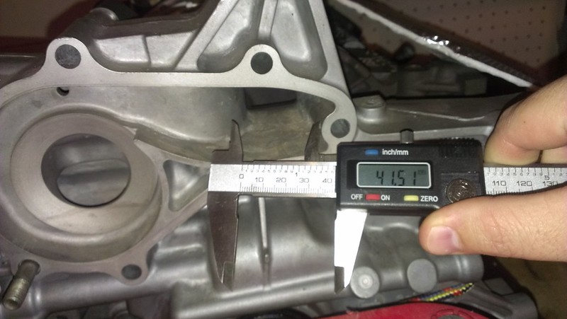
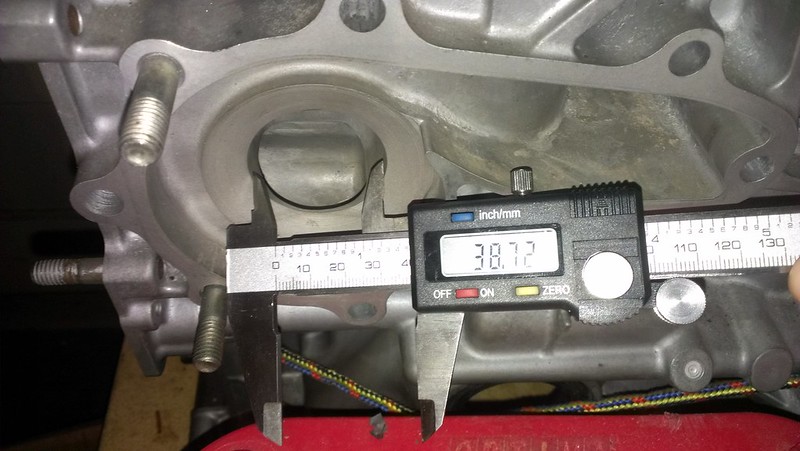
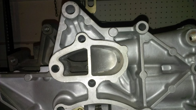
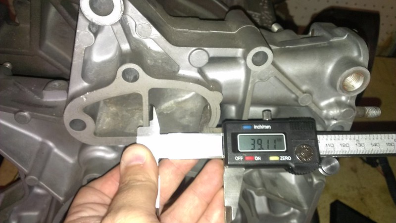
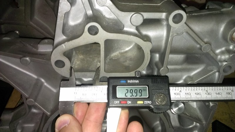
Hello all! I just started a little side project of modeling the stock water pump of the RX8, and I need the measurements of the inlet and outlet of the water pump. This is in an effort to help us figure out a high quality estimate the actual flow of the stock system, and to find out exactly where cavitation begins. To do that, I need a moderately accurate model of the inlet and outlet to the pump.
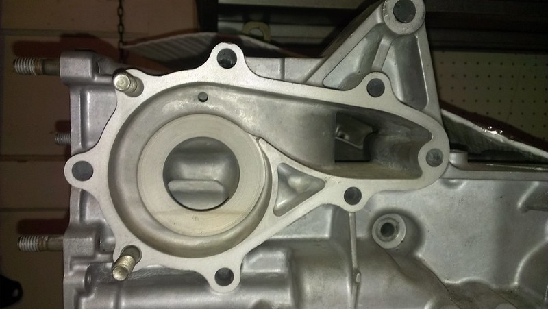
Here's someone elses picture of the coolant passages:
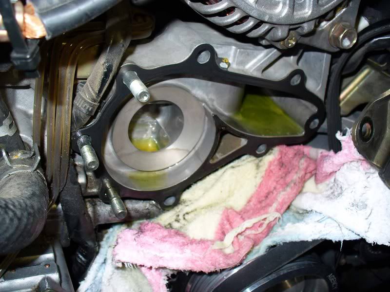
All that I need are five measurements, they are:
Width of the exit passage (on the right)
Length from the bump (separating the exit passage from the round part) to the gasket
Diameter of the inlet passage (circle on the left)
Length from the outer edge of the wear ring (big circle on the left) to the gasket
If anyone has a dry Renesis (either series) or is changing out their water pump/has it out, these measurements would really be helpful. It's ok if they're a millimeter or so off it won't make an appreciable difference.
Hello all! I just started a little side project of modeling the stock water pump of the RX8, and I need the measurements of the inlet and outlet of the water pump. This is in an effort to help us figure out a high quality estimate the actual flow of the stock system, and to find out exactly where cavitation begins. To do that, I need a moderately accurate model of the inlet and outlet to the pump.
Here's someone elses picture of the coolant passages:

All that I need are five measurements, they are:
Width of the exit passage (on the right)
Length from the bump (separating the exit passage from the round part) to the gasket
Diameter of the inlet passage (circle on the left)
Length from the outer edge of the wear ring (big circle on the left) to the gasket
If anyone has a dry Renesis (either series) or is changing out their water pump/has it out, these measurements would really be helpful. It's ok if they're a millimeter or so off it won't make an appreciable difference.
Last edited by Legot; 09-29-2014 at 04:10 AM.
#2
While this will likely be of little, if any, utility for your purposes, I gave it the old college try.
The measurements are corrected for the angle of the image.
Wow, thoroughly boned this up - I forgot that after measure #2, the units change from pixels to mm's since I set the scaling at that time. So my spread sheet is all outta wack (what I have listed as length in pixels is for measurements 3-12 actually in mm's).
Last edited by poacherinthezoo; 09-10-2014 at 11:19 PM.
#5
Thanks for the attempt poach! I thought about doing the same thing, but decided it would be easier and more accurate to ask here, just in case, lol.
And thank you 9k! It's so awesome that you were willing to do this for me! I'll be sure to publish what I find, know that it might take a while because my computer is slow, and CFD takes much longer than you might think.
For those who might not understand what I'm doing, I'm modeling the flow coolant through the water pump and the impeller in a 3D modeling software (Autodesk Inventor). Once the flow is modeled it can be married to the model of the impeller. This combined model can then be imported directly into a computational fluid dynamics program (Autodesk Simulation CFD). The CFD program can spin the impeller and calculate it's effect on the coolant at any rpm, pressure, point along the blade, or point the impeller. This is actually really CPU intensive (not GPU), so it takes a looooooong time.
With the data from the simulation, we'll be able to see the exact point and condition where cavitation starts (it can direct export a nifty gif-like animation), along with some lovely graphs and stuff.
If anyone wants the same done for, say, the Re-medy water pump, send me a PM with as many accurate measurements of the impeller that you can get. It might not be responsible to post the exact dimensions of an easily machinable part on the internet... It would be a nice comparison to see exactly what their pump improves on, and how much.
#6
cavitation starts around 6000 ish rpm, it's well documented by Mazda.
Mazmart already did that years ago and you can get that pump from them right now.
on stock pump, constant 9K rpm will overheat your engine. after the swap to Mazmart part its no longer the issue.
Mazmart already did that years ago and you can get that pump from them right now.
on stock pump, constant 9K rpm will overheat your engine. after the swap to Mazmart part its no longer the issue.
Last edited by nycgps; 09-11-2014 at 09:55 PM.
#7
Personally I'm interested in the flow rate and efficiency, but anything that I find out is going to be put out there for the good of the people.
#8
If anyone is curious as to what CFD looks like (I'm assuming most people haven't done it) this is a screenshot. In this view you can't really tell, but it is being modeled in 3space through the entire water pump.
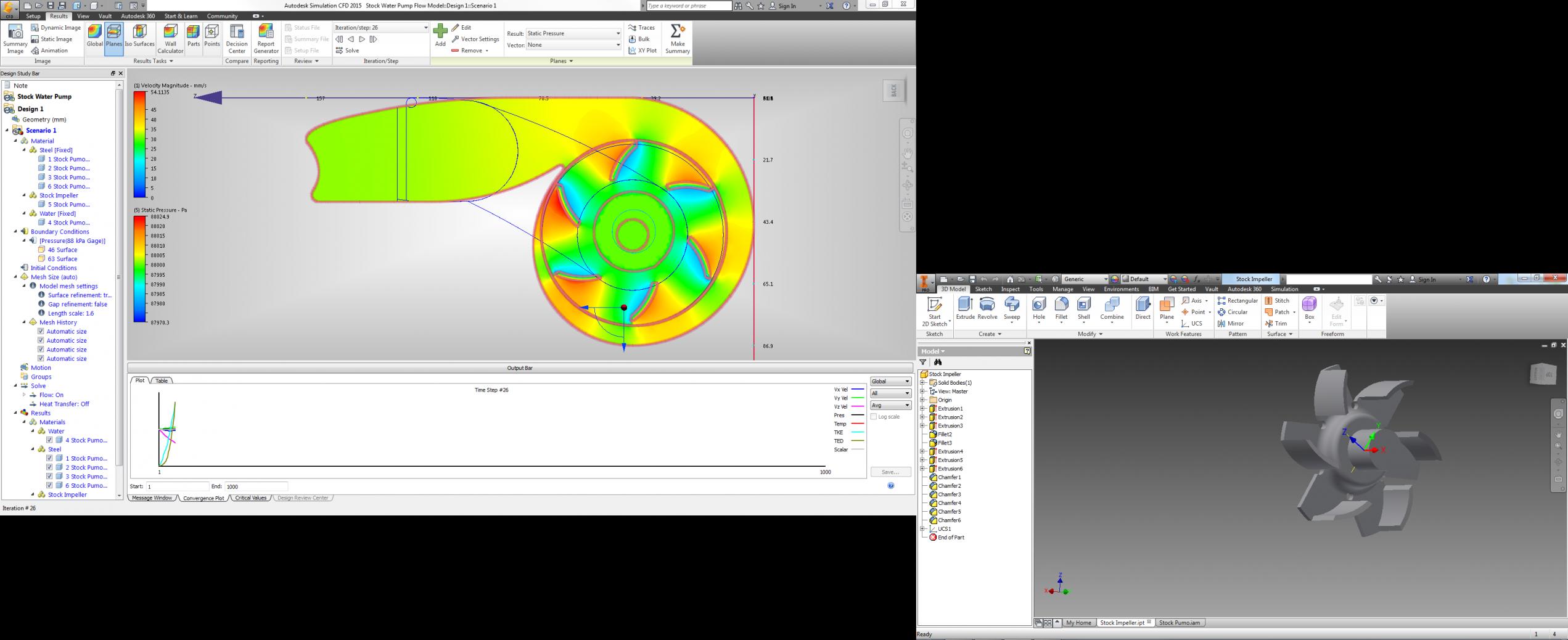
I'm currently running a test model now, just 1000 steps. It should run the pump up to just 0.5 RPM. I'm just using this to make sure everything is working right before I let it take up a computer for several days running it from 0 to 15000 RPM. As you can see, the impeller placement is off by about 1mm, so that will get fixed before the big model.

I'm currently running a test model now, just 1000 steps. It should run the pump up to just 0.5 RPM. I'm just using this to make sure everything is working right before I let it take up a computer for several days running it from 0 to 15000 RPM. As you can see, the impeller placement is off by about 1mm, so that will get fixed before the big model.
#9
This is pretty cool. I'm very interested in what the flow is in terms of gallons per minute. I'm switching to a remote external pump and that info will make selecting the appropriate pump much easier.
#11
I am curious if Mazmart ever did this type of thing. I kind of doubt they did but it's possible. Honestly I never noticed a difference with my Mazmart pump over the stock pump (updated latest version) so I was never convinced it was worth it.
I have a mazmart pump here, would you like any measurements?
I have a mazmart pump here, would you like any measurements?
Last edited by 9krpmrx8; 09-13-2014 at 12:09 AM.
#12
Sure, that would be awesome! I doubt that it really increases flow, but it is presumably much better than stock from a cavitation standpoint. If mazmart has quantitative analysis they either would have used it as promotional material, or kept to themselves if wasn't too impressive. It will good to have data available.
#13
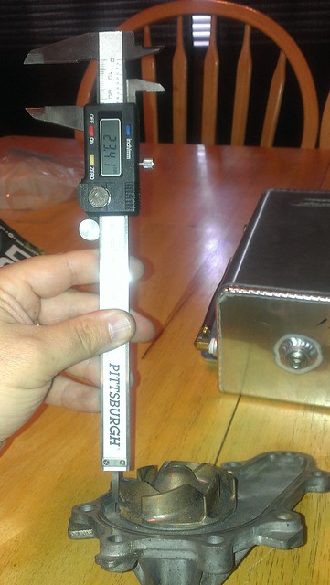
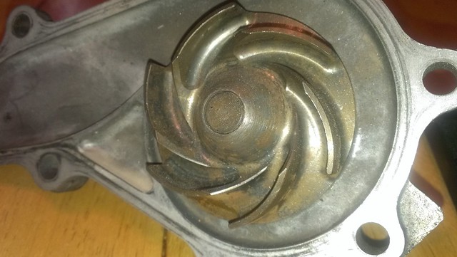
Okay, not sure if I got everything you need so let me know if I missed anything. Sorry for the crappy pics, I had no one to hold stuff so all I got was shaky cell phone pics, lol.
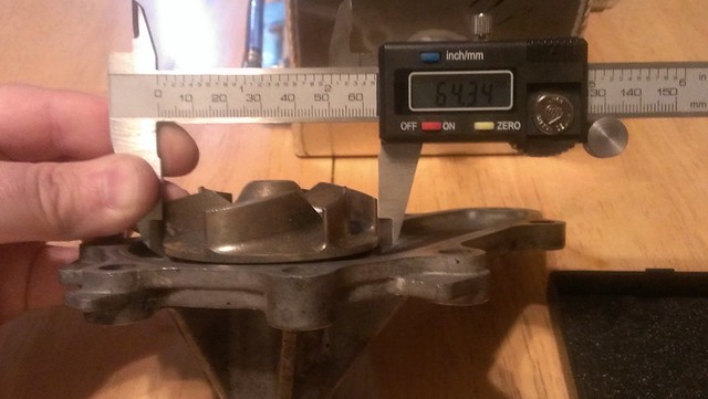
Even with the top of the center of the impeller.
Close up of mazmart impeller.
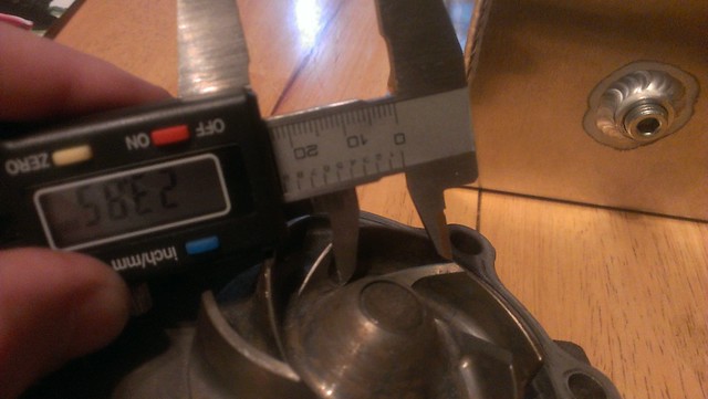
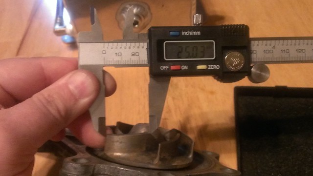
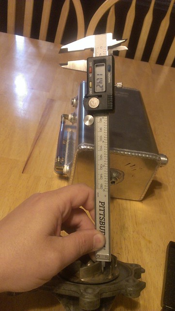
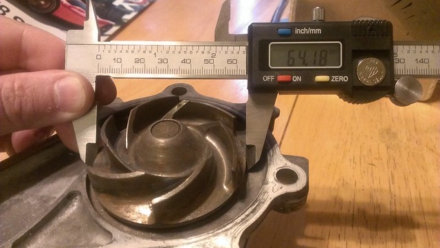
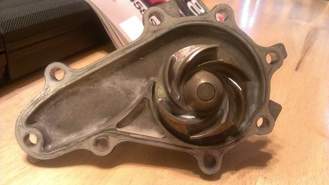

Even with the top of the center of the impeller.

Close up of mazmart impeller.


Last edited by 9krpmrx8; 09-14-2014 at 03:03 PM.
#15
Oddly enough, I have the same... ehem *calipers* and table as well. I still have my battery hatch though.
Thanks again 9k!
Finally started CFD on the Stock pump, and the Mazmart impeller is modeled to the best of my ability (anyone with a CNC mill want the part file ?) The stock results from to 15k rpm should be done by tomorrow afternoon (almost 17 hours to calculate everything), but who knows how long it will take to get it to output inlet and outlet velocities correctly.
Once that's done, the mazmart pump is ready to go!
Thanks again 9k!
Finally started CFD on the Stock pump, and the Mazmart impeller is modeled to the best of my ability (anyone with a CNC mill want the part file
 ?) The stock results from to 15k rpm should be done by tomorrow afternoon (almost 17 hours to calculate everything), but who knows how long it will take to get it to output inlet and outlet velocities correctly.
Once that's done, the mazmart pump is ready to go!
Last edited by Legot; 09-15-2014 at 02:33 AM.
#17
So I had to restart it a couple of times and for a while I had the impeller spinning backwards but as it stands we're at step #4040 out of 4500 steps, it looks like cavitation started at ~7200rpm (at ~10k now) and flow is currently ~180L/min.
Does anyone know the pulley ratios? The rpms that I'm using aren't engine rpms, they're impeller rpms.
I should be back with useable numbers in 3 hours or so.
Does anyone know the pulley ratios? The rpms that I'm using aren't engine rpms, they're impeller rpms.
I should be back with useable numbers in 3 hours or so.
Last edited by Legot; 09-18-2014 at 07:05 PM.
#18
Results
Evening fellow rotary enthusiasts!
As a recap, this data has been gathered in an effort to model, simulate, and compare the differences in flow between the stock Rx8 water pump and the Remedy Water pump sold by Mazmart! The software used to model the flow through the housing and the impeller was Autodesk Inventor Professional 2015. The computational fluid dynamics package used to simulate the transient flow was Autodesk Simulation CFD 2015.
Each simulation was done under a specific pair of boundary conditions being: 88kPa static pressure (the pressure allowed by a functioning radiator cap), and a temperature of 84.44 degrees Celsius (the target coolant temperature of the stock thermostat). The fluid flow was made of a simulated material that is (in all measurable properties distilled water in order to create a standard. Cavitation is less likely in the majority of coolants due to their higher viscosities.
Cavitation data is not directly available from the simulation, however the amount of cavitation is represented by the combined rate and magnitude of the oscillations in rotating power. This is due to vapor bubble regions forming (water molecules being ripped apart from one another, using a significant amount of power), and the same bubble regions imploding (rapidly decreasing the volume in front of the proceeding blade, sucking it forward with great force).
Here is a brief analysis of some of the results, there is more data available but this is all that is in a presentable/understandable format right now. Oddly, I'm not allowed to upload Excel documents on this forum, so if you really want the summary data then shoot me a pm and I can email it to you.
First up is Power vs Engine RPM!
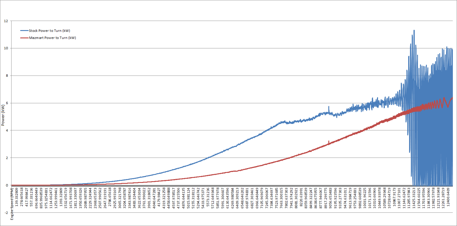
As you can see from the graph of the stock impeller (blue), there are two main points where cavitation begins, that is at 7735 RPM and 9300 RPM. From 7700 RPM to 9300 RPM there is a serious drop in the transmission of power from the impeller to the flow, suggesting a primary cavitation. A secondary, much more violent cavitation occurs at 9300 RPM and freaking skyrockets from there. Note that the average power would be linearly increasing after 9300 RPM
The graph of the Mazmart impeller shows a significantly lower power usage, and a much more controlled cavitation event.
Next is Flowrate vs Engine RPM (the one everyone cares about)

The data for this portion was tricky, and excel refused to interpolate or make a best fit curve, but this is it. The outlying point at 11700 Engine RPM is some sort of significant change in the vapor bubble region, but should be ignored when analyzing flow.
At 9300 RPM (stock redline), the Stock Impeller is capable of flowing 490 l/min (130 G/min).
At 9300 RPM, the Mazmart Impeller is capable of flowing 345 l/min (91 G/min).
These last two should really be transposed, but excel was giving me issues so I just let it be.
Stock Flow Rate vs Power
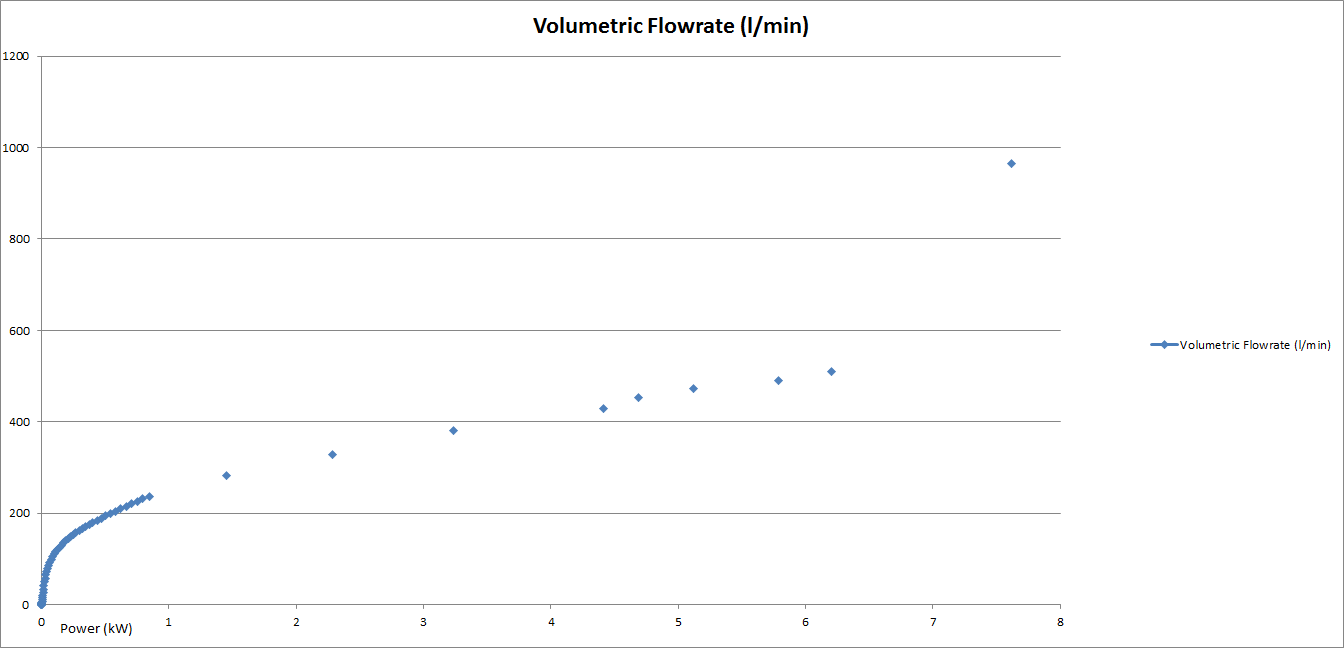
Mazmart Flow Rate vs Power

As we've already seen, the Mazmart impeller has a much more consistent power usage, along with significantly less power consumption. For both impellers as flow increases power usage increases exponentially (as expected).
Animation of the cavitation volume fraction of the Stock Pump
Mazmart Pump
The stock redline of 9300 Engine RPM occurs around step 225/300 (shown in the bottom left corner). Each step in the animation is ~150 RPM increase at the impeller or a ~125 RPM increase at the ES.
Now for some provocative facts and notes.
These two simulations were run as accurately as possible, however they are aimed at the max capabilities of the pump itself. It would be very nearly impossible to determine the exact flow rate through the entire coolant system (well, it's possible, but it would take months of simulations). Fortunately coolant systems are designed to flow as much as reasonably possible, which means that the flow data is likely within a +15% margin of error.
The Mazmart impeller flows less than the stock impeller under all conditions. However the efficiency of the stock impeller is less beyond 11000 RPM.
The Stock impeller cavitates more than the mazmart impeller from 7300 RPM onwards.
The curves along the blades on the mazmart impeller are quote simply eccentric circles, offset 60 degrees, the same diameter as the impeller (suggesting that someone with literally no impeller design knowledge made it).
The full disk type lower disk of the mazmart impeller is designed in such a way that the pressure differential on either side will decrease bearing life (not significantly, just a note on poor design choices)
The smoothed edges and gentle of the mazmart impeller are a major contributing factor to it's great cavitation performance at higher RPMs.
Above 11000 RPM, the cavitation of the stock pump would likely cause visible damage to the water pump housing/bearings over time.
As a recap, this data has been gathered in an effort to model, simulate, and compare the differences in flow between the stock Rx8 water pump and the Remedy Water pump sold by Mazmart! The software used to model the flow through the housing and the impeller was Autodesk Inventor Professional 2015. The computational fluid dynamics package used to simulate the transient flow was Autodesk Simulation CFD 2015.
Each simulation was done under a specific pair of boundary conditions being: 88kPa static pressure (the pressure allowed by a functioning radiator cap), and a temperature of 84.44 degrees Celsius (the target coolant temperature of the stock thermostat). The fluid flow was made of a simulated material that is (in all measurable properties distilled water in order to create a standard. Cavitation is less likely in the majority of coolants due to their higher viscosities.
Cavitation data is not directly available from the simulation, however the amount of cavitation is represented by the combined rate and magnitude of the oscillations in rotating power. This is due to vapor bubble regions forming (water molecules being ripped apart from one another, using a significant amount of power), and the same bubble regions imploding (rapidly decreasing the volume in front of the proceeding blade, sucking it forward with great force).
Here is a brief analysis of some of the results, there is more data available but this is all that is in a presentable/understandable format right now. Oddly, I'm not allowed to upload Excel documents on this forum, so if you really want the summary data then shoot me a pm and I can email it to you.
First up is Power vs Engine RPM!

As you can see from the graph of the stock impeller (blue), there are two main points where cavitation begins, that is at 7735 RPM and 9300 RPM. From 7700 RPM to 9300 RPM there is a serious drop in the transmission of power from the impeller to the flow, suggesting a primary cavitation. A secondary, much more violent cavitation occurs at 9300 RPM and freaking skyrockets from there. Note that the average power would be linearly increasing after 9300 RPM
The graph of the Mazmart impeller shows a significantly lower power usage, and a much more controlled cavitation event.
Next is Flowrate vs Engine RPM (the one everyone cares about)

The data for this portion was tricky, and excel refused to interpolate or make a best fit curve, but this is it. The outlying point at 11700 Engine RPM is some sort of significant change in the vapor bubble region, but should be ignored when analyzing flow.
At 9300 RPM (stock redline), the Stock Impeller is capable of flowing 490 l/min (130 G/min).
At 9300 RPM, the Mazmart Impeller is capable of flowing 345 l/min (91 G/min).
These last two should really be transposed, but excel was giving me issues so I just let it be.
Stock Flow Rate vs Power

Mazmart Flow Rate vs Power

As we've already seen, the Mazmart impeller has a much more consistent power usage, along with significantly less power consumption. For both impellers as flow increases power usage increases exponentially (as expected).
Animation of the cavitation volume fraction of the Stock Pump
Mazmart Pump
The stock redline of 9300 Engine RPM occurs around step 225/300 (shown in the bottom left corner). Each step in the animation is ~150 RPM increase at the impeller or a ~125 RPM increase at the ES.
Now for some provocative facts and notes.
These two simulations were run as accurately as possible, however they are aimed at the max capabilities of the pump itself. It would be very nearly impossible to determine the exact flow rate through the entire coolant system (well, it's possible, but it would take months of simulations). Fortunately coolant systems are designed to flow as much as reasonably possible, which means that the flow data is likely within a +15% margin of error.
The Mazmart impeller flows less than the stock impeller under all conditions. However the efficiency of the stock impeller is less beyond 11000 RPM.
The Stock impeller cavitates more than the mazmart impeller from 7300 RPM onwards.
The curves along the blades on the mazmart impeller are quote simply eccentric circles, offset 60 degrees, the same diameter as the impeller (suggesting that someone with literally no impeller design knowledge made it).
The full disk type lower disk of the mazmart impeller is designed in such a way that the pressure differential on either side will decrease bearing life (not significantly, just a note on poor design choices)
The smoothed edges and gentle of the mazmart impeller are a major contributing factor to it's great cavitation performance at higher RPMs.
Above 11000 RPM, the cavitation of the stock pump would likely cause visible damage to the water pump housing/bearings over time.
Last edited by Legot; 10-14-2014 at 10:45 PM.
#19
Can someone change the title of this thread to something like "Quantitative Coolant Flow Simulation" please?
Now, everyone feel free to discuss opinions. IMO, it is a total waste and kind of a modest step backwards to "upgrade" to the Mazmart impeller.
Now, everyone feel free to discuss opinions. IMO, it is a total waste and kind of a modest step backwards to "upgrade" to the Mazmart impeller.
Last edited by Legot; 09-29-2014 at 04:11 AM.
#20
Wow those are some pretty interesting results. Good stuff.
I guess the next interesting thing to know would be what volume of flow is most effective for removing heat.
Also pretty cool to finally know how much horsepower the water pump consumes. Almost 7BHP at redline is more than I thought it would be.
I guess the next interesting thing to know would be what volume of flow is most effective for removing heat.
Also pretty cool to finally know how much horsepower the water pump consumes. Almost 7BHP at redline is more than I thought it would be.
#24
Thanks very much legot.
Arca, I think best cooling is subjective to total system flow and the radiator you have.
I would be really interested in seeing how much is flowing through the throttle body and heater core. To know how much you are just recirculating and getting hotter. Also how much flows through the thermostat bypass hole.
Maybe a thermostat model to see how much it could flow. I bet that is a significant restriction.


