When you click on links to various merchants on this site and make a purchase, this can result in this site earning a commission. Affiliate programs and affiliations include, but are not limited to, the eBay Partner Network.
Yeah, I think my sample rate is just way too low lol... I am a newb and learning as I go...
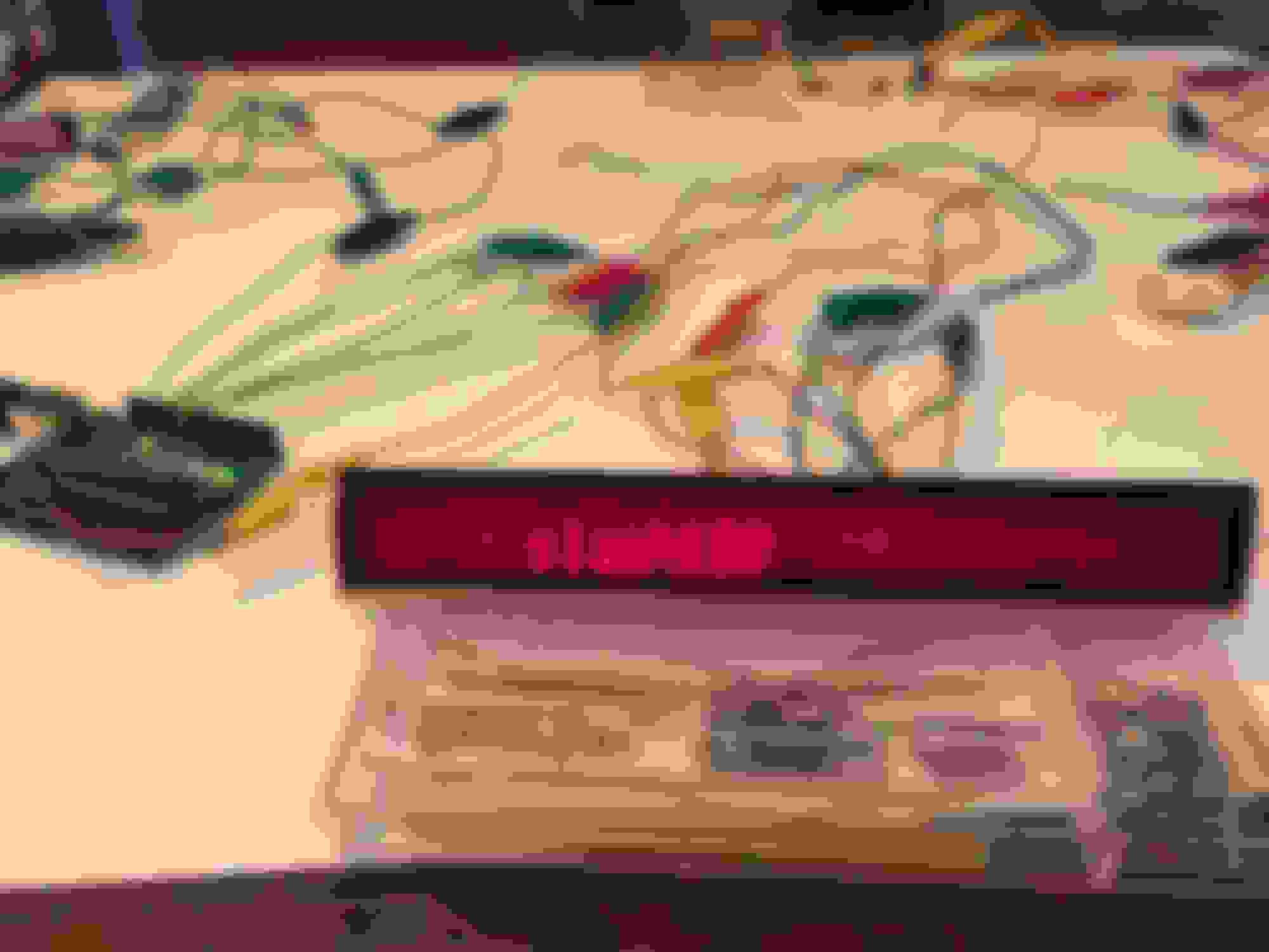
I'll give increasing my sample rate a shot... In the meantime, I just verified I could tie several of the lines together and the LCD still operated. At this point I believe I should be able to run the LCD without the head unit, if I can just get my code correct :-)
EDIT: I have confirmed the display can be run without the head unit with the following connections. The modes listed earlier in this thread were reversed, which hung me up for awhile
EDIT EDIT: After pondering a bit more, perhaps the modes aren't flopped, but their reference to the chip pins is flipped, ie: Purple is mode0, which is actually AC and not RS...
LCD Board Connector PIN
1) Red = VLCD1? - I believe so at this point - Tied to +8.0V with Orange
2) Yellow = VDD +5V Chip Power - Tied to +5.0V with Purple/Black 3) Blue = Mode0
4) Purple = Mode1
5) White = SPI CS
6) Brown = SPI CLK
7) Green = SPI MOSI
8) White/Black = LCD Shield - Tied to Ground 0V with Grey and Black
9) Purple/Black = +5V - Tied to +5.0V with Orange
10) Grey = VSS 0V Chip Ground - Tied to Ground 0V with White/Black and Black
11) Orange = LED Backlight V+ (+8V) - Tied to +8.0V with Red
12) Black = LED Backlight Ground - Tied to Ground 0V with White/Black and Grey
Hi Slash128,
It's been a while since you posted this, but I was curious if you might have something documented on how to interact with the Display over SPI.
I personally own a 2010 Mazda 5 (or Premacy as it is called in most countires), but I think the way the display works is pretty much the same.
As I replaced the original Radio with a JVC model, half of the display is quite useless now since a few years.
After I got my hand on a 2006 Navigation system that allows me to install another screen into the dashboard (most likely powered by a Raspberry PI), I thought this would be ideal to also get the original LCD back to life.
The RasPI does of offer an SPI Interface and I am sure it could provide some usefull information on this display.
Let me know if you have anything you can share, that would be great
Quick post here to share a post I made over on the old GOODbox group buy thread about a little adapter board I designed that replaces the GOODbox's internal boost pressure sensor and enables you to use an external, remote GM 3 Bar MAP sensor instead.
Realy great Job. I am looking forward to do something similar in the german Mazda6 (2003). I just wanted to please you to give me some hints. For example do you know the "Pinout" (Controll signals) of the Boardcontroller Display? How exactly have you decoded the canbus? What hardware did you use for decoding the canbus messages and generating the new signals? Do you know the connector signals?


 11-08-2016, 11:51 PM