Log In
Register
Forums
Vendors and Group Buys
Group Buy Center
Vendor Forums
Vendor Classifieds
General Topics
New Member Forum
RX-8 Discussion
RX-8 Multimedia/Photo Gallery
General Automotive
Website-related Suggestions
Series I Tech & Performance
Series I Tech Garage
Series I Trouble Shooting
Series I Do It Yourself Forum
Series I Aftermarket Performance Modifications
Series I Major Horsepower Upgrades
Series I Engine Tuning Forum
Series I AT-Specific Performance Mods
Series I Wheels, Tires, Brakes & Suspension
Series I Exterior Appearance and Body Kits
Series I Interior, Audio, and Electronics
Series II Tech & Performance (US 2009MY-)
Series II Technical and Trouble shooting
Series II DIY
Series II Aftermarket Performance Modifications
Series II Forced Induction and Nitrous
Series II Engine Tuning
Series II Wheels, Tires, Brakes & Suspension
Series II Exterior Appearance and Body Kits
Series II Interior, Audio, and Electronics
RX-8 Competition
RX-8 Racing
RX-8 Show and Shine
Drifting
Engine Swap Forum
Rotary Swaps
Non-Rotary Swaps
Regional Forums
Rotary Owner Events
NE RX-8 Forum
SE RX-8 Forum
MW RX-8 Forum
Gulf RX-8 Forum
Mountain Forum
West RX-8 Forum
NW RX-8 Forum
Canada Forum
Europe Forum
Australia/New Zealand Forum
Far East/Asia
Latin America
RX-8 Classifieds - PRIVATE SALES ONLY - Dealer Ads Prohibited
Bubbletech Fundraising Auction
RX-8's For Sale/Wanted
RX-8 Parts For Sale/Wanted
Good Guy/Bad Guy
Gallery
Tools
Car Payment Calculator
Tire Rim Calculator
Vin Decoder
Recalls
Technical Service Bulletins (TSBs)
Members List
Live Feed
Marketplace
Vendor Directory
Become a Vendor
New Posts
View Dark Mode
Please register or login to enable Dark Mode.
Log In
Register
Threads
Google
Threads
Posts
Advanced
Dark Mode
Please register or login to enable Dark Mode.
Log In
Forgot your Password?
By logging into your account, you agree to our
Terms of Use
and
Privacy Policy
, and to the use of cookies as described therein.
or
Login with Facebook
Recent
Commented
Albums
My Pictures
My Post Pictures
LFX_RX8
March 15, 2023
123
0
Sort:
Default
Default
Most Recent
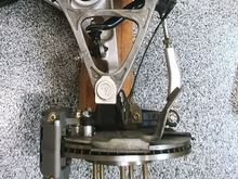
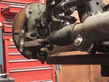
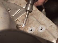
There is no requirement to press out the front wheel bearings to replace the front wheel studs. The hub can be removed with four bolts and the bearing assembly comes with it. However, there is no requirement to remove the hub. Instead, I just pressed out the studs with a ball joint separator and the new studs can be pulled through the hub with a Lisle stud installer and a impact wrench. Also shown in this picture is the adapter bracket used to mount the new Wilwood superlite caliper to the exis
0
2023/03/26 09:49:58
130521
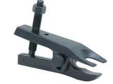
This is a photo of the ball joint separator tool I used to press the original studs out of the front wheel hubs. I purchased this from Harbor Freight and while some folks have had issues with theirs, this tool worked exactly as intended for my application.
0
2023/03/26 09:50:06
130521
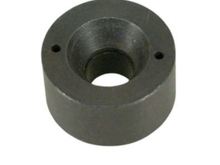
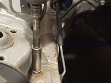
This is a picture of the Lisle 22800 wheel stud installer. I purchased the one I used from Amazon. Again, I found this to work very nicely. I can't remember but I think I used some additional washers between this and the wheel hub to enable me to use the original wheel lugs to pull the extended length new studs into the wheel hubs.
0
2023/03/26 09:55:12
130521
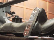
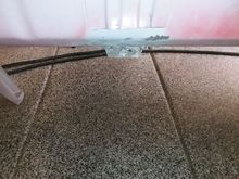
After removal of the existing steering rack assembly, the spacer supplied with the kit is attached to the existing steering rack mounting location. Note: The straight spacer is used on the drivers side of the front subframe. These bolts are torqued to 70 ftlbs.
0
2023/03/26 10:46:36
130521
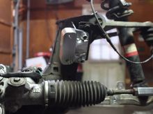
Similar spacer attached to the passenger side of the front subframe. Note: This spacer has a curved cutout which is necessary for clearance of the electronic power assist unit with is part of the steering assembly. Again, these bolts are torqued to 70 ftlbs. Also, you will need a thin wall socket to get down onto these bolt heads.
0
2023/03/26 10:46:40
130521
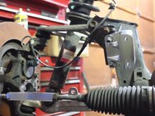
Then the original steering rack is reinstalled on top of the new mounting brackets. The steering rack bolts are torqued down to 70 ftlbs. In this photo the steering tie rod end locking nuts have been slightly backed off and the tie rod has been removed.
0
2023/03/26 10:46:46
130521
This photo shows installation of the new tie rod on the drivers side of the steering assembly.
0
2023/03/26 10:47:19
130521
Similar image of the installed tie rod on the passenger side of the steering assembly.
0
2023/03/26 10:47:22
130521
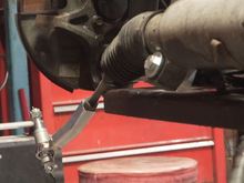
Passenger side tie rod installed into the knuckle. Note: The new tie rods supplied in the kit provide a number of different spacer configurations which allow some latitude to eliminate/minimize potential bump steer due to the relocation. Also, observe the orientation of the solid aluminum rod in the new tie rod. This section needs to be rotated so that the bent section is facing aft as shown in this picture. If it is facing forward, there is a good chance that it will rub against the inner wal
0
2023/03/26 10:47:26
130521
Following removal of the original antisway bar. The new antisway bar positioning brackets are installed on the front frame at the original mounting locations. The mounting bolts are torqued to 50 ftlbs. Note the orientation of the new brackets.
0
2023/03/26 11:08:00
130521
Similar installation of the new antisway bar bracket installed on the passenger side of the subframe. Again, these are torqued to 50ftlbs.
0
2023/03/26 11:08:05
130521
This picture shows the new antisway bar installed to the new aluminum adapter plates. A couple things to notice, the C-clips and bushings from the original antisway bar are removed and used with this new antisway bar. As Andrew points out in his installation video, you want to make sure to center this sway bar prior to torquing down this sway bar with a torque of 50 ftlbs. I later found that if the car was on the lift with the suspension fully unloaded (full droop)... I had contact between the
0
2023/03/26 11:08:12
130521
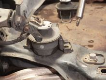
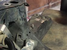
The original RX8 hydraulically damped engine mounts are removed from each side of the front subframe. You don't want to try and pry these out of the car while the engine is in the chassis. If you get under the hydraulic bladder with anything that can out a stress concentration on the bladder. If can and may fail if you do... ask me how I know.
0
2023/03/26 11:26:49
130521
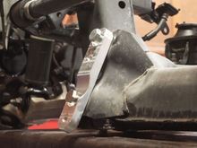
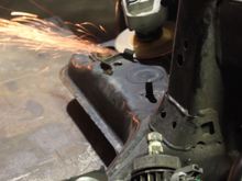
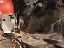
Then you want to take an angle grinder with a cutoff wheel and remove the guide bracket welded to the existing subframe.
0
2023/03/26 11:26:58
130521
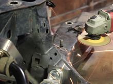
Use the face of the grinding wheel to grind the bracket stubs to a flat surface for the new engine mounts.
0
2023/03/26 11:27:05
130521
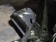
Similar picture showing removal of the passenger side guide bracket.
0
2023/03/26 11:27:14
130521
Again, you need to use a grinding wheel to eliminate the excess metal left after bracket removal. After the surface has been flattened and the new engine mount fits nicely in the modified hardware. The exposed metal surfaced should be primed and painted with a reasonable quality automotive paint.
0
2023/03/26 11:27:21
130521
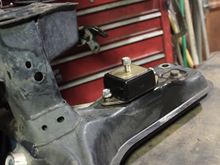
Picture showing the passenger side poly engine mount (supplied in the swap kit) installed in the subframe. At this stage of the process, the engine mount bolts are left loose to enable easier installation of the LFX engine. Once the LFX engine is installed on the engine mounts, the engine mount bolts can be torqued down.
0
2023/03/26 11:27:37
130521
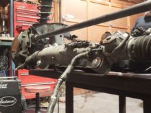
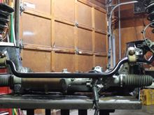
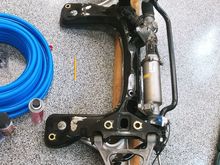
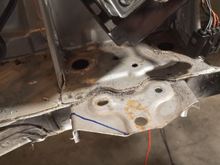
Mostly front view of my subframe after installation of the steering assembly and new anti-sway bar. While I have removed the original engine mount guide brackets and ground down the surface, I have not primed and painted the surface or installed the new poly engine mounts.
0
2023/03/26 11:44:01
130521
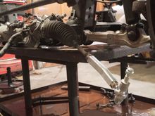
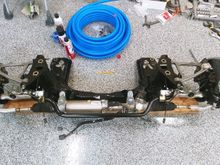
Top down view of my subframe after installation of the steering assembly and new anti-sway bar. While I have removed the original engine mount guide brackets and ground down the surface, I have not primed and painted the surface or installed the new poly engine mounts.
0
2023/03/26 11:44:05
130521
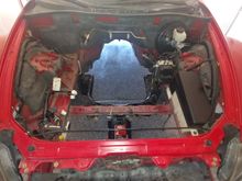
The original engine has obviously been removed. However you can also see that the inlet airbox, radiator and cooling fans have been removed. The battery box. and electrical control box have been removed from the front passenger side of the engine bay. The air pump assembly and it's control have been removed from the tower strut area on the passenger side of the engine bay. Finally, the wind shield washer fluid reservoir has been removed from the passenger side firewall.
0
2023/03/29 10:23:58
130521
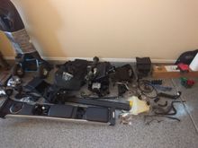
Picture of many of the parts removed from the engine bay. Lower far right are the coolant hoses. Side those is the windshield washer reservoir. Above the hoses are the RX8 coil packs and plug wires, and some pulley belts. Above that is the battery box. To the left of those are the intake airbox hardware. Directly below the airbox are the airpump and electronic control box hardware. Most of the rest of the hardware are interior console, and trim hardware. Except for the spare tire kit, and the
0
2023/03/29 10:24:02
130521
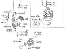
This is a parts breakdown of the RX8 air pump assembly. We really only need a few parts from this. Those include the air pump bracket 13-920, the resistor 18-831, and the rubber mounting hardware 13-331A, 13-343, 13-363, and 9973-0508
0
2023/03/29 10:24:16
130521
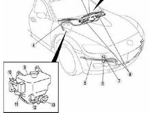
Location and illustration of the wind shield washer reservoir. Note: There appear to be multiple versions of this part so your part may look slightly different than this one. This part is removed to make room for the new engine coolant reservoir that is provided as a part of the LFX swap kit.
0
2023/03/29 10:24:28
130521
0
2023/03/29 11:06:25
130521
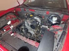
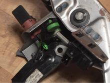
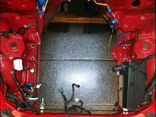
This photo shows the an overall view of the modified engine compartment after much of the charges had been made. It is obvious here that the insulation/sound cover has been removed. The engine compartment cleaned up nicely as shown in this photo. Additionally, you can see that the brake power booster, brake master cylinder and antilock/traction control brake system module have been removed.
0
2023/03/30 08:57:22
130521
Whether you have the automatic or manual transmission version of the RX8, you will get a new Wilwood clutch master cylinder as a part of the swap kit. This part is required because the Camaro six speed manual transmission clutch throwout bearing actuator requires more hydraulic force than the RX8 clutch master cylinder can manage. However, the Wilwood master cylinder requires a slightly larger access hole. So, you will need to open up the existing access hole about 1/8 of an inch.
0
2023/03/30 08:58:51
130521
0
2023/03/30 08:59:01
130521
The next order of business is to remove the subframe mounting/alignment pins from the engine compartment chassis. You need to do this to enable movement of the subframe while it is in close proximity to the chassis during reinstallation. Since these subframe mounting pins are tack welded to the chassis, you need to lightly grind down the tack welded region. You want to remove most of the weld but you don't want to cut into the chassis.
0
2023/03/30 08:59:18
130521
Once each of the subframe mounting bolt welds have been ground down. You can use a impact wrench to break these bolts free of the chassis. I used a old electric impact wrench for this and the welds broke free without much resistance
0
2023/03/30 08:59:22
130521
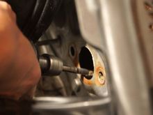
This photo shows the clutch master cylinder access hole after it has been opened up. As you can see, when I was opening up this hole, it was easy for the grinding bit to walk out of the hole and scrape the paint. I suggest grinding a little bit and test fitting the new Wilwood clutch master cylinder until it slides cleanly through the widened hole. Then debur the modified hole. I lightly sanded the area, cleaned it and applied a coat of primer and red paint to match the existing body paint pri
0
2023/03/30 09:11:15
130521
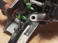
Before installing the clutch master cylinder, you can loosely assemble the clutch pedal assembly to the clutch master cylinder outside of the car. This allows you to adjust the actuator rod to the proper length so that the mounting pin will easily slide through the mounting hole when it is under the dash. There is not a lot of room under the dash and this makes installation of the brake pedal easier after the clutch master cylinder has been installed.
0
2023/03/30 09:17:29
130521
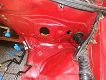
This picture shows holes which result from removal of the drivers side subframe mounting/alignment pins which normally reside below the ABS module. Again, after lightly sanding and cleaning these holes, I applied a primer and paint coating to this region before I began the installation.
0
2023/03/30 09:43:00
130521
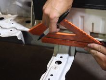
This photo shows marking the top location to cut the battery support brace.
0
2023/03/30 10:26:27
130521
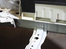
This photo shows the target cut line for the top of the battery support brace on the drivers side of the car. Note: You want to walk softly here, you don't want to cut into the chassis frame when making this cut. While not shown here, I similar process is used to mark the bottom of this brace prior to using a angle grinder with a cutoff wheel to remove the brace.
0
2023/03/30 10:26:30
130521
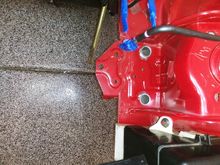
Here is a photo of my car after the cut and removal of the brace. This is the drivers side of the car which should be obvious due to the appearance of the bottom side of the fuse panel in the top of the half of the picture. Again, after this brace was removed, I lightly sanded the affected area, primed it, and applied a coat of read paint to protect the cut surface from future rust/corrosion.
0
2023/03/30 10:27:12
130521
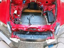
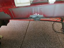
This photo shows the other side of the engine compartment after removal of the battery support brace. Again, you want to be careful not to cut into the frame rail. This is the passenger side of the engine compartment. The rubber coated tube in this photo is the remaining AC line between the firewall and the expansion valve mounted to the front rail of the engine compartment.
0
2023/03/30 10:27:17
130521
This photo shows the brake module mounting pad with the target cut line marked on the top section of the pad. Not shown in this view is the vertical cut line where the pad material is doubled up. This provides a nice vertical cut line to trim this pad.
0
2023/03/30 10:43:45
130521
This photo shows use of an angle grinder with a cutoff wheel to remove the target region of the brake module mounting pad.
0
2023/03/30 10:43:50
130521
This top down view illustrates the removal of the four subframe mounting/alignment pins, elimination of the battery support brace across the engine compartement, and trimming of the brake module support bracket.
0
2023/03/30 10:43:58
130521
First
Page
3 of 4
Last
Go To
Page
1
2
3
4
3 of 4
Go To
GO
Go to page
of 4
pages
1
2
3
4